The Studeblogger

Saturday, March 09, 2013

Advanced Distributing for Studebakers.

That little part above is, as you probably know, a vacuum advance canister (or "spark modifier" in Studebaker parlance" for a Delco distributor of the type used on Studebaker V8 Larks from 1960 to 1961. Although only used by the factory during those two years, the "window-type" Delco is prized by many Stude drivers because it's easy to rebuild, get parts for, and set point gap on, compared to the Prestolite units used on other years.

As detailed in an earlier post, I obtained and rebuilt one of these Delcos, using a core graciously given to me by Warren Webb, one of the regulars on the Studebaker Drivers Club Forum.

At the time I built it, however, I installed a vacuum advance specified for a 1961 Impala, figuring (wrongly) that a vacuum can is just a vacuum can. I should have known better! What I've found out since is that not all cans are equal. On this Forum thread, Joe Hall notes that the can commonly sold for Studebaker applications (NAPA VC680) is actually 2 degrees shy of the Studebaker OEM advance setting for V8 cars.

It turns out that nearly all of these vacuum advance units are all manufactured by Dana Engine Controls, now owned by Standard Motor Products, so no matter what brand you buy, it's the same part in the box. The trick is determining the right part. And there are about 25 different cans, each with a different setting for the point at which full advance kicks in. So how do you identify them?

Dana stamps a number on the mounting bracket of each advance unit. Each number corresponds to an advance profile that denotes how much vacuum must be applied to achieve full advance. It turns out, according to Joe Hall's research, that the Studebaker part number is "B20." The VC680 that NAPA's system specfies is "B1". Obviously the wrong part.

Insufficient advance can be responsible for lost power and poor gas mileage - both of which my Barney has exhibited. So I started digging to find out what part number was correct for the Studebaker distributor. VC1765 turns out to be the correct Stude part.

Thanks to the guys on the Corvette forums, who know their stuff when it comes to Delco parts, I found out the difference in the two parts' advance delivery settings:
  • VC680 (stamped "B1") delivers 0 degrees of advance until 8" of vacuum, and 16 degrees of advance at 16" of vacuum.
  • VC1765 (stamped "B20") deliver 0 degrees of advance until 6" of vacuum, and 16 of advance at 12" of vacuum.
So the part I had on the car started delivering advance too late, and full advance came in waaaaay too late. No wonder I was getting crappy mileage! B20, by the way, is the unit used on high-performance GM engines. I take a bit of pride in knowing that. (According to a very scholarly treatise on vacuum advances written by Lars Grimsrud of TunedbyLars.com, B26 carries the same specs as B20 and may be found in the same box.)

So I went to my friendly local NAPA and ordered a VC1765. Wisely, I  checked the part before leaving the store - the wrong part was in the box, with a hand-written label that had another part number on it! Always check. Another part ordered, and this time it was correct - B20 stamped into the boss.

Replacement is easy, and doesn't require removing the distributor from the car. Just unplug the coil wire and undo the two spring-loaded screw clamps that hold the distributor cap on, and move it out of the way. The screws that hold the vacuum advance to the distributor base are accessible from the passenger side of the car once the cap is removed.

As you can see in the photo above, there are two screws holding the advance unit on. Use a magnetized screwdriver to remove them, otherwise you'll be cussing as you remove the distributor to fish them out after you've dropped them! Also note that a lug attached to a wire that grounds the breaker plate is located under the screw at the end of the actuating rod - you'll need to replace it there after installing the new advance.

After the screws are removed, pull the advance unit out; the actuating rod will then be able to rotate out of the hole in the breaker plate by pulling the advance body upward.

Installation, as they say, is the reverse of removal. Once it's all back together, don't forget to check the timing and reset the idle if need be.

For some interesting reading about vacuum advance, check out this post from the Vetteclub Forum, and the aforementioned paper from Lars Grimsrud. You'll find out everything you need to know and more!

Labels: , , , ,

Tuesday, August 14, 2012

Adjusting Idle Mixture on the WCFB

Idle mixture is an important setting on a carburetor, and most people don't know how to do it. What you're trying to do is set your carburetor's idle circuits for the most efficient operation with the least fuel.

There's no better tool for doing this than a vacuum gauge. It can also tell you a lot about the health of your engine; it's really an invaluable tool. For a great walk-through of how to use a vacuum gauge for diagnostics, check out this tutorial from Greg's Engine & Machine, of Copley, Ohio.

But for setting the idle mixture, there's nothing like actually seeing it done. Here's a short video tutorial I put together, showing idle mixture adjustment using a vacuum gauge on my '63 Lark with 259 and WCFB 4bbl. As you'll see, it's simple and fast - all you need are a tach, vacuum gauge, wrench and screwdriver.


Now go get 'er done!

Labels: , , ,

Saturday, June 18, 2011

Valve Adjustment for the Studebaker V8

Well, I finally set aside the time to adjust Barney's valves, and got it done today. I should have done this right after the rebuilt engine was brought back to life, but I was hesitant because the job intimidated me, and after all, the car was running, right?

But solid-lifter valves need to be properly adjusted in order to maximize efficiency and power. And Barney's gas economy has been, shall we say, less than stellar. I knew it was needed and overdue. Actually "valve adjustment" is a misnomer -- you're not adjusting the valves themselves, but the valvetrain "lash," or the air gap between the rockers and valve stems when the valves are closed.

Of all the maintenance operations in Studebakerdom, I think this one may be the source of the largest amount of questions, concerns and fear. But I learned that it's much easier to actually do the adjustment than it is to read about it! You just gotta get your hands dirty, and it all makes sense. Part of the problem, I think, is that the process is often described, but never illustrated. You'd think that a common operation like this would be thoroughly documented on the Web, but it isn't - so I hope the following illustrated tutorial will help future Studebaker seekers.

The Studebaker V8 in its natural habitat

It'll take about 2 hours to do the job in your garage, if you work like I do. You'll need a spark plug socket, a good set of feeler gauges, a socket set, a 1/2" wrench and a test light. A remote starter switch is useful too. A tube of anti-seize and silicone grease will come in handy for reinstalling the spark plugs, but they're not necessary.

First, you need to know the firing order of the Studebaker V8, because you have to adjust the valves in that order.


Firing Order:
1-8-4-3-6-5-7-2

As the illustration shows, the left bank of cylinders (driver's side) has the "odd" numbered cylinders (1,2,5 & 7), while the right bank has the "even" cylinders 2,4,6 & 8), so you'll be moving back and forth from side to side during the adjustment process.

After much reading of various folks' recommendations for adjusting the valve lash, I decided to stick with the factory method outlined in the Studebaker shop manual. Studebaker gives a proceedure for adjusting the valves either with the engine hot and running, or stone cold. I chose to do it cold, since I don't like the idea of working on a hot running engine, especially one that's flinging oil around like a congressman spends cash!

To start, I numbered the spark plug wires prior to removal so that I'd get them right upon reinstallation, and pulled them off.

Then, I removed the valve covers. This is accomplished by removing the nuts from each of the two studs that exit each cover. I laid them across the air cleaner so that I wouldn't have to remove the wires from the built-in clips on the covers. On the left-hand valve cover, there's a spring that provides return tension to the throttle bellcrank; I unhooked this from the bellcrank and kept it with the valve cover.


After the valve covers were off, I removed the spark plugs. I like doing this with the valve covers off, as it provides more room to work. The #6 plug is a little fishy to work around due to the close proximity of the oil dipstick tube; #7 is also a bit tricky because of the master cylinder plumbing. Just work gently to avoid cracking the spark plug insulators during removal and reinstallation.


All my plugs looked good - normal deposits and nice and clean, except for the plug from #5 cylinder (3rd from left, above), which had some crusty ash deposits on it. The spark plug guide chart says this is due to a bit too much oil in the cylinder during combustion; I'll have to watch this - could be a leaky valve guide seal.

By the way, I'm a big believer in an orderly workspace :)

Now to perform the first valve adjustment. This is done by finding the Top Dead Center of cylinder #1. Top Dead Center is also called "firing position;" it's the point in the engine's rotation just after the compression stroke, during which the spark plug ignites the fuel charge in the cylinder. It's also the point at which both exhaust and intake valves are completely closed.

To find TDC for #1, I connected a remote starter switch to rotate the engine easily. The Studebaker vibration damper has several marks stamped into it; one reads "UDC 1". (UDC stands for Upper Dead Center - Studebaker stuck with this older terminology to the end.) When this mark is exactly under the timing pointer, #1 is at TDC.


BUT there's a caveat: in a 4-stroke engine, the cylinder is at the top of the bore on both the compression AND the exhaust stroke. You need to make sure the TDC you're finding is the one just after the compression stroke.The easiest way to do this is to put your thumb over the #1 plug hole and rotate the engine with the remote switch. When your thumb gets blown off the hole, that's the compression stroke! Stop spinning the engine. You'll rotate the engine the rest of the way to TDC by hand - it turns pretty easily with all the plugs out.

If you have a fixed radiator fan, you can grab the fan blades and turn in order to ease the engine to TDC. But this won't work on engines with clutch-type fans. SDC Tech maven Dwain Grindinger wrote in one of his how-to pieces that you can use a socket wrench on the alternator (or generator) pulley to turn the engine, and it works! I also grabbed the crankshaft damper with my right hand and gave it a turn while using the wrench with my left. This provides the leverage and control needed to move the engine a small amount at a time.

 
Once you've found TDC for #1, it's time to adjust the valve train. Studebaker mandates a clearance of between 0.025" and 0.027" for cold engine adjustment; I split the difference and adjusted to 0.026". to do this, you simply slip the blade of the feeler guage between the valve stem and the surface of the rocker arm; the adjusting nut is on the opposite arm of the rocker. These are pretty stiff; they're self-locking adjusting nuts so there's no locking nut to loosen - just put your 1/2" wrench around it and go!

 
If the feeler slips right into the gap, great. If not, you'll need to loosen the adjusting nut - turn it counter-clockwise to open the gap. You want to feel a bit of resistance as you pull the gauge through the gap, but not too much -- "the feeling should be about the same as putting a table knife through a stick of cold butter," according to an excellent article on valvetrains I found on the Century Performance website. All my valves were tight, and had to be opened up in order to get the gauge in. once it's there, though, small adjustments to the adjuster nut achieve the proper resistance very quickly.

Finding TDC is easy with cylinder #1, since its position is marked right on the vibration damper. How do you find TDC for the other cylinders? That where the test light comes in. Look at your ignition coil and find the wire that leads from the coil to inside the distributor - NOT the high-tension wire that leads from the center of the coil to the center of the distributor; the wire you're looking for is a thin (likely black) one that is screwed to one of the two small terminals on the coil. It leads inside the distributor to the points. Connect one of the leads from your test lamp to the post this wire is screwed to; connect the other end of your test lamp to a clean ground.


Now put your key in the car's ignition and turn it on -- No, not to "START"! Just the first click, to the ignition "ON" position. Now, as you rotate the engine (by hand), the test lamp will illuminate when the distributor's points close. When that happens, you've found Top Dead Center for the cylinder you're going to adjust.

Remember the firing order? You've just adjusted cylinder #1. Next in the firing sequence is #8, so rotate the engine by hand until the test lamp just lights, and adjust both valves for cylinder #8. Continue to hand-turn the engine and set the valve lash for cylinders 4,3,6,5,7 and 2.

After the first couple of valve sets, the process gets incredibly easy. Before you know it, you're done! Now it's time to put it all back together.

If your spark plugs are all in good shape, clean them and inspect the gap. I like to smear a little silver anti-seize on the threads to ease removal and protect the threads in the head; I also put a bit of silicone lube inside the spark plug wire boot to make sure they seal well and come off easily later.

Put the valve covers back on, reconnect the plug wires and fire it up - you're ready to go!

After adjusting the valves, Barney came to life immediately and ran like a top. The difference was amazing - not only did he idle smoother, he warmed up faster. ON the road, there was less engine vibration, and he revved quicker. Also, the usual smell of fuel was missing during my test drive. (I knew Barney was blowing fuel out the back because the exhaust tips are sooty...) My son and I took him for a full-throttle blast through a nearby industrial park (empty on the weekends), and the difference in performance is dramatic -- I actually got rubber in 2nd gear.

After doing a valve lash adjustment, be sure to check your timing afterward, as valve adjustment affects timing. I will actually need to lower my idle, since the engine is running so much more efficiently now that the idle speed is noticeably increased.

I hope this brings some clarity to a mysterious procedure, and helps other newcomers to the Studebaker hobby!

Labels: , , ,

Monday, January 17, 2011

Oil Change.

OK, really? A how-to post on changing your oil? Who doesn't know how to do that? Well, maybe. But stick with me; this tale has a surprise ending.

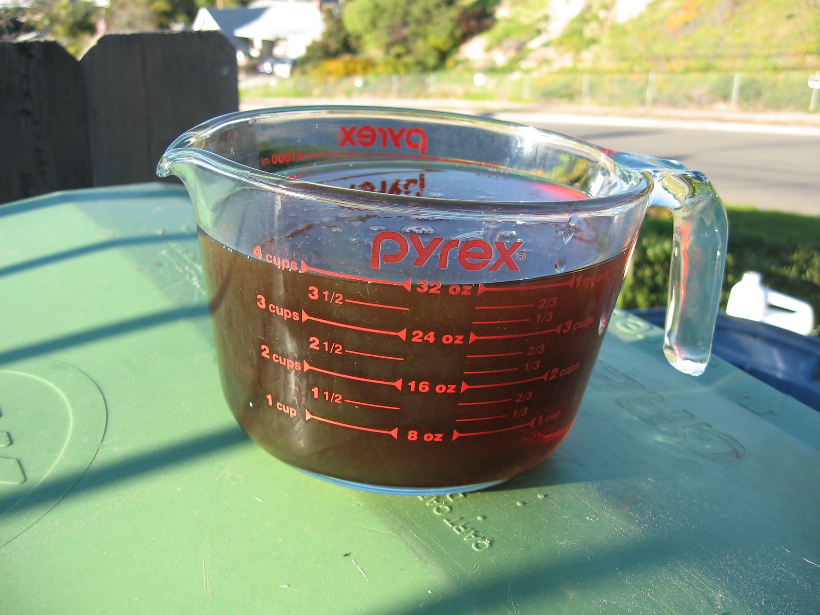
With 500 miles on the clock since commissioning his rebuilt engine, it was time to change Barney's break-in oil. For break-in, I had run a load of precious Service-CI4 formula Shell Rotella T (with a full load of ZDDP to protect the solid lifters in the Stude's engine), accompanied by a pint of GM Assembly Lubricant for extra break-in lubricity (ooh! $5.00 word!).

Oil changes, the traditional way, are messy, dirty jobs. You pull the drain plug from the pan, get splashed with hot, dirty oil, lose the plug in the bucket of hot, dirty oil, realize you forgot to pick up a new package of plug gaskets... So a while back, I purchased a Pela oil vacuum specifically to avoid all of this.

The Pela is great. All you have to do is push its pickup tube down your dipstick, attach the pump and give it about 10 strokes. In seconds, you see the tube fill with black gold and it begins to flow into the vacuum canister. OK, it takes a little time... the 5 liters in Barney's sump took about an hour to pump out. But that's about the same time you'd take to make certain everything finished dripping out of the oil pan -- and with a lot less mess.

After cooling it, the deed was done and the engine had given up its filthy load of black lube. Nasty stuff for only 500 miles! But break-in is where all the rough edges inside a rebuilt engine get smoothed over, so the break-in oil is necessarily ugly.

So we're ready to pour in the new oil -- uh, no. Gotta change the filter first.

The oil filter on the car is a Purolator Premium Plus 30005. It's a full-quart unit that is rated very highly. Unfortunately, I couldn't find another in the area. But my NAPA supplied a Mobil 1 M1-203; it's a 3/4 quart filter, but has an upgraded element to handle the nasties.

Some guys just use the old screwdriver-jammed-through-the-can tool to remove old oil filters. I've tried that - once - and didn't like it. Too messy. Plus, the cans tend to tear; bad scene there.

I found this genuine ChannelLock oil filter pliers in the discount bin at NAPA for $5.00. You can't beat that deal with a stick! I like these better than the strap wrench because they "bite" the can but don't destroy it. The adjustable slip joint makes it easy to get a good grip. A little loosening and the filter spins right off.

Remember, that thing's full of dirty dino juice, so be sure you have a tub under the filter when you loosen it. A goodly amount of greasy goop will spill out once you undo it, too, since the system is under pressure.

You can probably get the filter off without raising the car (if you're skinny enough), but I like a little more elbow room. I chocked the rear wheels, lifted the front, and rolled under with my creeper in comfort.

Notice in the photo above that the oil filter can is located directly over the passenger's side exhaust pipe. This is significant, because it means that --

Right. Studebaker engineers routed the exhaust pipe directly beneath the oil filter mount, virtually guaranteeing that I'll be smelling smoke for 20 miles until the oil burns off the pipe.

The good news is that, while I was down there, I found the two nuts that hold the flywheel inspection cover to the bellhousing were a bit loose, so I tightened them up. Don't forget to put a few drops of oil on the gasket of the new filter, and remember to spin it on hand-tight (not finger-tight!), or you'll wind up with a big grease spot on your driveway in pretty short order.

Now, here's the surprise I promised: if you go by the capacity chart in the Owner's manual, you'll be shy a quart of the honey gold. Yep, the Studebaker manual for 1963 lists the capacity of the engine (both 6 and 8) as 5 quarts. But if you put only 5 quarts in the engine, the dipstick will tell you you're a quart low. I know, because I measure out my oil before pouring it in.

The guys on the SDC Forum have confirmed this quirk. Perhaps it was a misprint, or a holdover from the old days when oil filters were accessories. Whatever the case, if you're doing a full oil and filter change, you'll need 6 quarts.

I always get a little knot in my stomach when I first fire up the engine after an oil change. There's always that little bit of apprehensiveness; the engine is spinning but the pressure gauge shows zero... and then, after a couple seconds, the needle shoots to its accustomed 60 pounds and stays there, the relief valve open and engine purring. Ahh... success :) Time for a drive!

Labels: , ,

Sunday, January 02, 2011

Head Bolt Torque, Revisited.

A while back I posted about checking and re-torquing head bolts on Studebaker V-8 engines. The Shop Manual contains all the torque specifications and the bolt tightening sequence (which I documented in my earlier post), but recently a thread on the Studebaker Drivers Club Forum made mention of an additional procedure worth noting. It's probably one that experienced mechanics take for granted, but I certainly don't fall into that category (and I know some of my readers don't either).

Specifically, the heads should be re-torqued when the engine is cold, and should be loosened slightly before tightening. Says Forum member Mike Van Veghten:
Always cold...at least 4 hours since the engine was run, cold.

This is important because the Shop Manual gives conflicting instructions, saying that one should warm up the engine "to stabilise the temperature" before checking head bolt torque. Mike explains that this is outdated thinking, and the reason to torque when cold is simple: the first few bolts torqued after running the engine will be to spec, but the engine immediately starts to cool, causing the metal to begin contracting. Bolts torqued after this process begins will be tightened to a different value than the first bolts you worked on!

Therefore, all bolts should be torqued to spec only when the fastened assemblies are cold. This includes valve adjusters.

Furthermore, Mike says:
Back each fastener out about 1/2 turn (one at a time), then re-tighten to the proper torque value. If you do not back the fastener out, you will not get the proper final torque put into the new tightening operation.

Now (as the saying goes), you know... the rest of the story!

Labels: , ,

Tuesday, September 07, 2010

Oil Breather Caps for late Studebaker engines

When you're detailing an engine, it's the little stuff that makes the difference. Decals are one thing that contribute, as are correct engine accessories. In my case, the oil breather/filler caps were one of the last things to need touching.

Studebaker converted to full-flow engines (that is, an engine where 100% of the lubricating oil is filtered) in late 1962. Prior to that, Stude V-8s were partial flow engines, meaning that not all the oil was filtered as it passed through the oiling system. The two engine types can be immediately identified by the location of the oil filler tubes and the valve cover design: partial flow engines have a filler standpipe front-and-center, forward of the valley cover, and the valve covers have no filler openings. Full-flow engines have oil fillers in the valve covers  and no standpipe on the block.

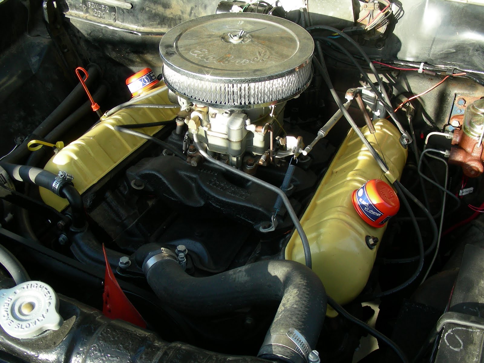
Compare the two photos below to see the difference: On the left is a V-8 installed in a '62 Lark; its central oil fill and solid valve covers mark it as a partial flow engine, while the '63 engine compartment on the left has the dual valve-cover-mounted fillers of a full-flow engine.


Regardless of the type of engine installed, notice that the oil filler cap is the same in each photo: a low-profile orange cap with a blue and white label. This cap, painted orange, was used on all standard '62 - '64 Studebaker engines. A chromed version was used on Jet Thrust engines installed in all Avantis, or on Larks and Hawks that had an optional JT engine. In fact, I believe the basic design of this cap dates back to the very beginnings of the Studebaker V-8; the photo below shows a cap of similar (if not identical) design installed atop the oil filler of a pristine 7,400-mile 1951 Commander State sedan.


Nevertheless, if your cap is missing, it is available as a reproduction from Studebaker vendors - but only with the chromed finish. I don't know why they don't offer a painted version, since there were far more non-JT engines produced over the years, but there it is. So if you have a pair, re-use them! Or get a used pair cheap, wash them up and refurb. Here's the quick-and-dirty makeover.

When I acquired Barney, his OEM Stude breathers were already long gone, ditched in favor of a set of Mr. Gasket chromies. These work find and look OK, but they sit high; the Stude breathers snuggle down over the filler pipe and sit close to the valve covers. So I procured a used set from an SDC Forum user and proceeded to strip off the old paint. The photo here shows an original breather alongside its twin, paint removed using a nylon abrasive wheel.

After the old paint's gone, the new goes on. The secret here is to use Dupli-Color DE1620, better known as Chevy Orange. It's a perfect match for the orange paint Studebaker used in several places under the hood on late V-8s. I always use a base-coat of Rust-Oleum red primer just to even things out; after that, the Orange goes on.

Not a bad result! This is after a coat of primer and two coats of Orange. Now the finishing touch: the decals. These are correct for 1961-1964 caps; older ones were painted only solid colors. The decals are basically STP advertisements (Studebaker acquired STP in '61 as the Corporation began to diversify). These labels are reproduced and can be gotten from Studebaker vendors.

There was some discussion on the Forum a while back as to which direction these labels were applied; some maintained that they went on so that the lettering could be read correctly with the cap installed; others swore that the labels were put on upside-down at the factory. I prefer mine right-side-up, so that's the way I put them on. It just makes sense that way, to me! The labels are self-adhesive, so no wetting and sliding of decals is needed. Here are the completed caps, ready to go.


Above are before-and-after shots of Barney's engine. On the left, the Mr. Gasket breathers. As I said, they're not bad. On the right, the newly-refurbed Studebaker caps. Notice how they hug the valve covers. Also, you can see in the photo below, the Dupli-Color orange really is a perfect match for the OEM paint: the Viscous Drive fan in the photo has factory-original paint and the difference, to my eye, is nil.


Happy Studebakering!

Labels: , , , ,

Tuesday, January 12, 2010

New coil, better spark.

Driving Barney around, I've been trying to figure out why there's such a strong fuel smell at times; I've gone through the whole fuel system and ruled out leaks, from the carb to the tank. Also, I've noticed hard starting, even after just a day of not being driven - much harder starting than fuel bowl evaporation could account for. Starting often required a loooong 10-second crank (to prime the carb, I'd assumed), followed by a second crank during which the engine would catch, crank a little more, then fire. Starting idle wasn't too smooth, either.

After thinking about it a bit, I started to focus on the coil. It's one of the few parts of the electrical system I hadn't touched. Looking at it, I found that it was a very old Delco-Remy. Was it OE? Who knows? At the very least, it wore two coats of black paint; one original and one from the engine bay repaint. There was rust showing on the case, and some corrosion in the tower. So I decided to replace it.

NAPA shows Echlin #IC12 as the OEM application for a '63 Lark, so I footed it down to my local store and picked one up last night. At lunch I went out and replaced the old Delco, and when I turned the key -- presto! Barney fired right up. This is noteworthy because my last drive was on Saturday, 3 days ago - plenty long enough for fuel to evaporate from the bowl and cause a hard-start condition if that's what the trouble was.

But with only one pump of the go pedal to set the choke, the engine caught with a healthy roar after only 3 turns of the crank, and ran smoothly at fast idle, just like it ought to. I think that the old coil, while still operative, was probably not putting out enough spark to economically run the engine, a problem the new coil solved.

Goes to show how sensitive gas engines are to good spark output, I guess.

Labels: , ,

Sunday, December 13, 2009

Bellhousing dial-in procedure,


One of the most mystery-cloaked operations in all of Stude-dom is the bellhousing dial-in. Known to make grown men shiver and quake with just the thought of doing it, this must-do strikes fear into the heart of even the bravest.

Well, maybe it's not that bad. But it certainly is something no one looks forward to, no matter how steeped in Studebakers they may be. And it's something that's unique to Studebakers - you don't have to do this with an old Ford or Chevy, so if you're new to Studes it's essential that you know about this.

So what is a bellhousing dial-in, and why is it needed? Long and short of it is that Studebaker's bolt-on bellhousings need to be aligned to the crankshaft center-line so that the crank and transmission input shafts are on the same plane. This keeps the torque converter (or flex plate, or clutch) from self-destructing as it revolves. Instructions are given in the shop manual, but nobody seems to really understand 'em.

SDC member Allan Anderson recently photographed and described this procedure. Bob Johnstone has archived it on his website for all posterity (or at least until the Chinese take over the Internet and outlaw all things Studebaker). Check it out and make a bookmark - if you ever have to change out a bellhousing, this is an invaluable reference.

Labels: , ,

Sunday, November 15, 2009

Hey... your head is loose!

While I've been occasionally accused of not having my head screwed on tight enough ;) I'm talking about the bolts on your engine's heads in this case.

StudeKen (Ken Pyle, who rebuilt my 259) reminded me that the head bolts needed to be re-torqued after the engine had been restarted and run a bit, which mine now has. So, yesterday being a beautiful 72 degrees here in SoCal, I decided on a little StudeWrenching in preparation for road-worthiness.

First step is pulling the valve covers. If you're a GM guy like I was, you're probably used to a lot of hold-down bolts around the base of the covers, as seen below on my '67 Pontiac. Some other brands have quite a lot more bolts!


In contrast, Studebaker valve covers are easily removed without fumbling around by just unscrewing the two bolts in the center of the valve covers (4 bolts on older models):


The studs protrude through the valve cover through rubber seals, easily available from SI and other vendors. Just undo them, and pull the valve cover off (after removing the spark plug wires, of course). The valve covers seal to the heads using re-usable, soft neoprene rubber gaskets, and they take a little pulling to get loose; don't be shy, just grab the oil filler tube and give it a gentle yank.


With the valve train exposed, you'll have easy access to all the head bolts. There are 18 of them, as shown in the figure below, taken from the factory Shop Manual:


The manual specifies 55-65 lbs.-ft. of torque for each bolt. I usually split the difference, and so set my wrench right in the middle at 60 pounds for this operation. Note that the diagram shows a specific sequence for tightening the bolts; although this is specified for head installation, I used it for the re-torqueing operation as well (better safe than sorry!) Note that the 5 center bolts under the valve cover get torqued twice.

I was surprised at how loose a few of these bolts had gotten with just some running-in-place in my driveway! They all broke loose with the first pull of the wrench, on average took a quarter turn before the wrench clicked to indicate torque. A couple of them took nearly a full turn, specifically the two furthest forward adjacent to the water manifold.


I used a 12" extension to get the proper leverage on the torque wrench for most of the bolts, but a couple - those furthest toward the firewall - needed a shorter extension to clear certain obstacles. On the passenger side, the flange for the heater plenum interfered; on the driver's side, the steering column forced using the 6" extension. I also had to shift the transmission's column shifter from Park to Reverse in order to drop the shifter linkage out of the way.


After you're done, the valve covers go back on easily. In the photo above, you can see the rubber seal iin its channel around the rim of the valve cover; make sure it's seated properly and not dropping loose, otherwise it could be cut by the interior flange and seal improperly - and there's nothing worse than engine oil dribbling onto your hot exhaust manifold while you drive!

The Stude shop manual calls for 14-20 inch-lbs. (!) of torque for the valve cover nuts. Now, maybe back in the day everyone had tools calibrated in inch-lbs. just lying all over the place, but here in the 21st century you're more likely to find a dinosaur bone in your backyard than such a device at your local Sears.
14 inch-lbs. is not a lot of torque, so I just used a nut driver to tighten the nuts hand-tight, which is all the neoprene seals really need.

All done! Put the spark plug wires back where they belong and DON'T forget to reattach the throttle return spring to the wire clip welded to the driver's side valve cover.

Update, January, 2011: There's a little additional information about proper torquing procedure. Check out this post.

Labels: , , ,

Sunday, September 06, 2009

How-To: Studebaker Delco Distributor Rebuild

If you've been following the past few posts, you've read of the self-destruction of Barney's Prestolite distributor, and my being gifted with a Delco distributor core (see A Drive To Perris). At first I thought maybe I'd send it off for a professional rebuild, but decided on doing it myself, mostly because I got antsy and didn't want to wait, but also because I was told what an easy job it was.

Amazingly, my searches of the Web turned up absolutely NO tutorials on how to go through a Delco distributor, so hopefully this will help others seeking this information. It's actually pretty simple. And here's a plug for the necessity of having the Studebaker shop manuals: the disassembly and reassembly instructions Studebaker provided are better documented and photographed than the procedure I found in my '67 Pontiac shop manual! If you are embarking on a Studebaker project, I strongly urge getting a set of Shop, Chassis and Body manuals for your car - they are absolutely invaulable.

Many folk associate Prestolite distributors with Studebakers, but in fact Delco spark-slingers were used on Stude V-8s through most of the 1950s and into the 60s. The advantage of the Delco is that parts are easier to come by; additionally, two model years (1960 and 1961) used the common Delco "window-type" unit that any GM fan is intimately familiar with. It's called a "window type" because the cap has a small metal "window" that can be slid up to facilitate setting the point dwell while the engine is running - a massively convenient perk. Another perk of running the Delco is that you don't have to get "the look" from the counter guy at your FLAPS* when you ask for Studebaker parts; you just tell 'em you need distributor parts for a '61 Impala and you're golden.

Bob Johnstone, the keeper of all Stude technical knowledge (check his tech site at www.studebaker-info.org, if you haven't already) posted the following numbers for Delco-Remy distributors with Studebaker applications. This number can be found on a stamped aluminum collar in a machined groove just below the distributor head:
  • 1110839 - All 1953, '54 and '55 V8
  • 1110864 - All 1958 & '59 V8, 1960 289 cu. in. V8 only
  • 1110869 - 1960 259 cu. in. V8 only
  • 1110969 - all 1960 cars w/V8 (except Hawk) & all 1960-61 trucks
  • 1110969 - 1961 259 cu. in. V8 only
  • 1110864 - 1961 289 cu. in. V8 only
  • 1110981- 1960 & '61 V-8 Larks, all (this is the "window-type" unit)
My Delco is a 1110981 - the desirable "window" unit. Although this is only correct for the two model years shown above, it will fit any 259 or 289 Studebaker engine. So, off we go!

My first step was to clean the sucker off. As you can see, the sucker had acquired a nice suntan of surface rust; Warren showed me a junk V8 engine he'd pulled it from. It looked like it had been outside without a cap for a while. But mechanically it was fine; the rotor shaft had no side play and runout between the drive gear and adjacent brass bushing was within the spec called for in the Studebaker shop manual (.036" - .068").

I pulled off the old points, condenser and vacuum advance, as well as the homebrew primary lead. With a little exercise and the application of some trombone slide oil, the breaker plate began to move freely, so I elected not to fully disassemble the unit by driving out the pins that hold the drive gear and oil pump drive shaft to the rotor shaft. The advance weights were hard to get off due to the light rust on their pins, but the trombone oil freed those up as well, and I stowed all the removed parts in Ziploc bags.

Since I'm the kind of guy that likes to make things look good as well as work well, I set to work with a Nyalox abrasive wheel. This is a "wire" wheel that's made of impregnated Nylon - it strips paint and rust quickly without harming the metal underneath or leaving that telltale "brushed" look on metal surfaces. I think I got mine at Home Depot, but you can buy them direct from the manufacturer, Divine Brothers.

I carefully unlocked the irreplaceable aluminum Delco tag from the machined channel and proceeded to buff off the surface rust. The Nylox wheels work with amazingly little effort, and in no time the distributor head casting was nice and shiny. The next step was to shine up the advance weight mounts, breaker plate and breaker cam.

On the advice of Jeff Rice, I used my Dremel tool with a small steel brush to clean the rust from the interior parts. The breaker plate appears to be chrome plated, so it was rust-free; the breaker cam and advance cam were another story. I cleaned up the advance parts first, getting all the rust off the surfaces that the centrifugal advance weights slide on. The advance pins had a little bit of wear on them. but not enough to render the distributor shaft useless.

I didn't want to touch the breaker cam with the Dremel wire wheel, so I used some 2,000-grit emery film to polish the rust off of it. Then, my favorite non-abrasive metal polish, Nevr-Dull, was used to further polish the cam and breaker plate. I love this stuff; it's basically a chemically-impregnated cotton wadding that removes rust and other staining from metal parts, depositing a thin layer of lubricant protectant as it works. Soon, the delicate bits were spic 'n span.

After that, I took the Nyalox brush to the two advance weights. They had sustained some pitting, but cleaned up well. Mr. Gasket and other speed-parts suppliers make replacement weights for these distributors, but I'd rather re-use than replace when possible :) With the upper bits clean, I put a small brass cup brush in the Dremel and cleaned the light rust out of the interior of the base casting using the large access hole in the breaker plate.

At this point, with everything cleaned up, it was time for paint. Using painter's tape, I masked off the moving parts and the section of the shaft housing that must remain plain metal. Note that there is a large hole in the bottom of the casting that allows the distributor primary lead to exit; you'll need to cover this from the inside to keep paint from getting into the mechanicals.

I like Rustoleum red primer because it's specifically formulated for rusty metal, and even though I'd cleaned all the rust off, there's no sense taking chances! After a couple of coats of primer, I shot it with black engine paint and let it dry overnight, followed by a second coat of engine black the next morning. By midday, the paint was hard and the tape came off. Things looked great!

I used a little dielectric grease to lubricate the advance weight pins and re-installed the weights. Note that the mounting holes in the weights are tapered; if you turn them over you can discern that the hole diameter is slightly larger on one side than the other. Slide them onto the pins with the large side down, toward the advance cam baseplate. Note that there is a small, button-like raised area in the baseplate that the weighs rest directly over and must slide upon; a little grease in this area is a good idea as well to keep them moving smoothly.


You can get replacement advance springs from a number of manufacturers; just ask for the kit for a '61 Chevy. I chose Mr. Gasket, although Moroso, Accel and others make them. I suppose your friendly GM dealer might have springs too (if he's still in business). The Mr. Gasket kit includes three different spring weights to customize your advance curve; on the advice of SDC member and distributor guru Harry "Bud" Alenik, I installed the gold OEM-weight set. Harry explains:

"Most of the aftermarket springs have more tension than the springs originally installed in stock Studebaker Delco distributors. Studebaker engineers specified full advance at 2400 rpm where most other manufacturers specified full advance somewhere above 4000 rpm. I've found that the guys at Studebaker had the advance set at an optimum point for good engine operation without detonation. I've found that by using the stock advance and setting the base timing around 8 deg. BTDC, that a stock V8 will make plenty of power without detonating. The R series engines still use the 2400 rpm full advance, but limit the amount of centrifugal and vacuum advance to keep the high compression engines from detonating."

Should you choose to play with your advance curve, I've documented the spring weights and the timing advance each set provides on this post.

 The next thing I did was to install the new vacuum advance unit (or "spark modifier", as the shop manual refers to it). I got this from NAPA, it's Echlin part #VC680. Wrong! The correct advance part is VC1765 - see this post for more. It's held on with two screws, one at the edge of the base and the other just under the edge of the breaker plate. To install it, you must rotate the breaker plate so that you can get the vacuum can's actuator rod into the hole in the plate. It takes a little maneuvering to get it in there, but once you get the rod at the right angle, it slides into the hole easily. I put in the screw that holds the unit to the rim to hold the unit in.

There is a black wire crimped to the breaker plate; this is what supplies ground to the points. I slid it under the head of the second vacuum advance attaching screw as shown in the pic to the right. If your ground wire has gone missing, you can get a replacement from NAPA; it's Echlin # LW42. It comes with two spade-lug ends; you can attach the other end under the nearby pointset hold-down screw instead of trying to crimp it to the breaker plate.

I installed a rubber grommet in the hole for the primary wire; this is just a standard 3/8" wire grommet that you can get from the bins at any hardware store.

With the advance unit in place, I installed the pointset. I opted for a "Uniset" combo unit; this is an all-in-one part that combines the breaker points and the condenser into one unit and eliminates fiddling with a separate condenser and lead. You'd think this would be an inexpensive part, but I found that as the use of points has decreased, the cost of pointsets has increased. NAPA wanted $35.00 (!) for the Uniset points; I opted instead to order them for half that price from Studebaker vendor Chuck Collins. They are Borg-Warner #A2120, although I'm sure other manufacturers have them as well. Chuck, as always, got the goods to me immediately; I ordered on Thursday and they arrived on Saturday. I also ordered two new distributor mounting gaskets.

Now that the points are installed, you've got to lube the breaker cam. This is also known as the "rubbing block", for obvious reasons: the points rub on the octagonal cam as it rotates; each time it rubs over one of the cam's corners, the electrical connection between the points is broken. Even though the bit of the pointset that contacts the rubbing block is plastic, without lubrication the block will wear. If you've never had a car with points before, you may not realize that there is a specific kind of lube for this, a silicone grease that is smeared onto the cam to protect it. This has to be renewed periodically, too, so it's good to have a tube around. My old tube of Lubricam has seen duty since the mid-'80s and still has plenty left. Bosch still makes it, as well as some other manufacturers, but you may have to go to a real speed shop to get it - the NAPA and Pep Boys near me have none in stock.

With lubrication taken care of, it was time to put on the rotor. Again, NAPA had the part, Echlin #RR1670. I opted for the Heavy Duty part, since the contact is constructed from heavier brass than the standard-duty part. In Delco distributors, the rotor fits right over the advance weights, covering them completely, and screws to the advance cam. On the bottom of the rotor are two lugs; one round, one square. They fit into corresponding holes in the cam so you can't install it 180ยบ reversed. Once the rotor is screwed down, hold the shaft and twist the rotor counter-clockwise; you should feel some spring resistance as it rotates; release it and it should snap back. This verifies that the molded webbing on the bottom of the rotor is not interfering with the operation of the advance weights and springs.

The last bit inside the distributor is the primary lead. I threaded this through the newly-installed grommet in the base and attached the spade lug to the screw provided on the front of the pointset.If you're missing the lead or yours is boogered up, go to NAPA and get Echlin part #LW67.

After that, it's time to install the cap. Unlike the Prestolite cap, which attaches with a pair of spring clips mounted to the base, the Delco cap has a spring-loaded hold-down on each side. A notch machined in the base of the distributor body accepts the tab molded into the bottom of the cap, which positively locates it and keeps it from rotating; simply place the cap on the base and use a flat-blade screwdriver to depress the hold-down, then rotate it so its ear is beneath the locating notch underneath the cap and release it; it will clamp the cap to the base. Repeat on the other side. The cap, by the way, was also gotten at NAPA: Echlin #RR1650. This is the matching heavy-duty cap for the rotor, with brass terminals instead of aluminum.

That's it! She's assembled and ready to be dropped into Barney's engine. I'm hoping I get the chance to do this tomorrow - stay tuned for further developments.

Thanks to Warren Webb, Jeff Rice, Bob Johnstone, Bud Alenik and all the guys at the SDC Forum for their help information.

*FLAPS -- Friendly Local Auto Parts Store.

Labels: , , , , ,