The Studeblogger

Saturday, March 09, 2013

Advanced Distributing for Studebakers.

That little part above is, as you probably know, a vacuum advance canister (or "spark modifier" in Studebaker parlance" for a Delco distributor of the type used on Studebaker V8 Larks from 1960 to 1961. Although only used by the factory during those two years, the "window-type" Delco is prized by many Stude drivers because it's easy to rebuild, get parts for, and set point gap on, compared to the Prestolite units used on other years.

As detailed in an earlier post, I obtained and rebuilt one of these Delcos, using a core graciously given to me by Warren Webb, one of the regulars on the Studebaker Drivers Club Forum.

At the time I built it, however, I installed a vacuum advance specified for a 1961 Impala, figuring (wrongly) that a vacuum can is just a vacuum can. I should have known better! What I've found out since is that not all cans are equal. On this Forum thread, Joe Hall notes that the can commonly sold for Studebaker applications (NAPA VC680) is actually 2 degrees shy of the Studebaker OEM advance setting for V8 cars.

It turns out that nearly all of these vacuum advance units are all manufactured by Dana Engine Controls, now owned by Standard Motor Products, so no matter what brand you buy, it's the same part in the box. The trick is determining the right part. And there are about 25 different cans, each with a different setting for the point at which full advance kicks in. So how do you identify them?

Dana stamps a number on the mounting bracket of each advance unit. Each number corresponds to an advance profile that denotes how much vacuum must be applied to achieve full advance. It turns out, according to Joe Hall's research, that the Studebaker part number is "B20." The VC680 that NAPA's system specfies is "B1". Obviously the wrong part.

Insufficient advance can be responsible for lost power and poor gas mileage - both of which my Barney has exhibited. So I started digging to find out what part number was correct for the Studebaker distributor. VC1765 turns out to be the correct Stude part.

Thanks to the guys on the Corvette forums, who know their stuff when it comes to Delco parts, I found out the difference in the two parts' advance delivery settings:
  • VC680 (stamped "B1") delivers 0 degrees of advance until 8" of vacuum, and 16 degrees of advance at 16" of vacuum.
  • VC1765 (stamped "B20") deliver 0 degrees of advance until 6" of vacuum, and 16 of advance at 12" of vacuum.
So the part I had on the car started delivering advance too late, and full advance came in waaaaay too late. No wonder I was getting crappy mileage! B20, by the way, is the unit used on high-performance GM engines. I take a bit of pride in knowing that. (According to a very scholarly treatise on vacuum advances written by Lars Grimsrud of TunedbyLars.com, B26 carries the same specs as B20 and may be found in the same box.)

So I went to my friendly local NAPA and ordered a VC1765. Wisely, I  checked the part before leaving the store - the wrong part was in the box, with a hand-written label that had another part number on it! Always check. Another part ordered, and this time it was correct - B20 stamped into the boss.

Replacement is easy, and doesn't require removing the distributor from the car. Just unplug the coil wire and undo the two spring-loaded screw clamps that hold the distributor cap on, and move it out of the way. The screws that hold the vacuum advance to the distributor base are accessible from the passenger side of the car once the cap is removed.

As you can see in the photo above, there are two screws holding the advance unit on. Use a magnetized screwdriver to remove them, otherwise you'll be cussing as you remove the distributor to fish them out after you've dropped them! Also note that a lug attached to a wire that grounds the breaker plate is located under the screw at the end of the actuating rod - you'll need to replace it there after installing the new advance.

After the screws are removed, pull the advance unit out; the actuating rod will then be able to rotate out of the hole in the breaker plate by pulling the advance body upward.

Installation, as they say, is the reverse of removal. Once it's all back together, don't forget to check the timing and reset the idle if need be.

For some interesting reading about vacuum advance, check out this post from the Vetteclub Forum, and the aforementioned paper from Lars Grimsrud. You'll find out everything you need to know and more!

Labels: , , , ,

Saturday, June 16, 2012

Light Up The Night.

Every so often someone posts to the SDC Forum asking about headlight aiming, so I thought I'd document some answers and useful links here.

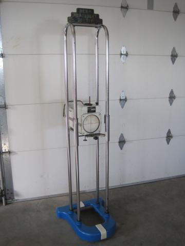
The high-tech, pay-someone-else-to-do-it method is to find a shop with a beamsetter. It used to be a lot easier to find these - remember the yellow Bear Headlight Alignment signs with the little laughing bear (that the Grateful Dead later copped) outside gas stations?

These items basically consisted of a unidirectional photocell that measured the candlepower of the light emitted by your headlamps. You pulled up square to the unit and adjusted the lamp until the focus of the beam produced the highest reading on the CP meter. (More about Bear Beamsetters here, if you're interested.)

Needless to say, these are rare birds in this day of sealed headlamp assemblies and halogen cartridge bulbs. So how do you aim an old Studebaker's lamps?

Daniel Stern in a guy who lives and breathes automotive lighting. His website has just about everything you'd want to know about bulbs, circuitry, output, regulations and more car lighting esoterica than you can shake a stick at. He has a wonderful, plain-language explanation of how to aim the bulbs on nearly any car - all you really need is a flat surface, about 40 feet of work space, a vertical wall and some painter's tape. Read it here: www.danielsternlighting.com/tech/aim/aim.html .

And while you're at it, maybe think about upgrading the headlamp circuitry on that old car. Another frequent question on the Forum is "Why do my headlights keep blinking on and off at night?" Generally, it's due to one of two things:
  1. That little booger on the left, there - a headlamp circuit breaker that's gotten old and weak, and is kicking off when the juice is applied, then back on as it cools down.
  2. The breaker is fine, but your wiring, switches and connections are old, and resistance in the headlamp circuit is so high that the breaker is doing its job, kicking off to prevent your wiring harness from turning into a mass of carbonized copper with melted plastic dripping off it.
Generally, it's a combination of the two. In old cars like ours, there is no headlamp relay - the juice to light you up goes straight through the headlamp switch in the dash, then back out to the front of the car. That's a long way for those electrons to travel, and there's loss along the way. (This is also, BTW, why your lights look dim and yellowish.)

The solution is to install a modern headlamp relay circuit. This takes the amps out of your dashboard and routes them directly from the generator/alternator to the bulbs, instead of taking the long way 'round through the Inland Empire (SoCal residents get the joke).

Daniel Stern also has a great article on how to do this, natch: read www.danielsternlighting.com/tech/relays/relays.html for the whole skinny.

Because there's nothing worse than being out for a nice cruise on a warm summer night... then having to feel your way home against the curb because your eyes suddenly went dark.

Labels: , , ,

Sunday, January 23, 2011

Woot! That was easy!

Followup to yesterday's post regarding the headlights not working: Fixed that! After studying the wiring schematic last night, I determined that the only place in which the problem could reside lay in the vicinity of the headlamp circuit breaker. So, this morning, I lay down in the floor (again) with the flashlight in my mouth (again) and, within 30 seconds, found a loose feed wire to the breaker! Apparently, all my rooting around with the ignition switch yesterday had caused the (already somewhat loose) barrel connector to slip free of the breaker stud. 2 minutes later, the wire was reconnected, the switch mounted in the dash, and Barney was idling placidly in the driveway.

Ah... one in the "win" column :)

Labels: ,

Dang it!

Had some time yesterday so got to do a little work on Barney. First up was changing out the old gas filler hose in the trunk, which was letting fumes into the passenger compartment. That went well, so I tackled another project: putting in a new headlamp switch and ignition switch.

I changed out the headlamp switch first and tested it; headlamps worked! Awesome! Then I swapped out the old ignition switch for a new replacement from SI. Put it all back into the dash, turned the key - car fired right up. Yay! Tested the headlights - no lights. Boo.

I had to go to church so didn't have time to figure out what was wrong, and just disconnected the battery for the night. Looking at the wiring diagram, I think either the headlamp breaker opened or... well, that's really the only thing I can figure. I'll have some time this AM, so it's back to laying on my back in the floor again :)

Labels: ,

Sunday, January 16, 2011

Better turn signal indications.

When I gave Barney his new wiring harness, I installed a full complement of brand-new instrument-panel bulbs of the type called out in the Owner's manual, #1445 bulbs in most locations. It quickly became apparent that at least two of them, the turn signal indicator and the Flight-O-Matic indicator lamp, were too dim to be seen in the daylight.

A Forum search turned up several threads on the subject, one of which is here. Folks in that thread recommended some other bulbs that would fit the space and provide more candlepower, so I tried those out and found them still wanting - I can barely see Barney's turn indicator when the signals are on.

So my Jameco catalog came and as I was leafing through it, I found LED replacements for bayonet-mount panel lamps - 12 volts at .30 milliamps. Unfortunately, searching their site turned up availability in only red or yellow LED colors, but a Google search found the white-light versions at Grainger. Grainger shows the LM-1012MB as a direct replacement for the 1445 bulb - for only $20 per item! I may not be a genuine CASO, but that's a little stiff for me.

Finally, another web search on the part number turned up a place called Bulb Town, whose site lists the LED "bulbs" for $13, a much more amenable price.  So I ordered a couple, which arrived in my mailbox last Thursday.

You'll notice that the package size of the LED is longer than the 1415 bulb that the factory used, but for in-dash lighting this is not a problem, as there is plenty of room in the gauge cases. I popped the LED bulb into the socket for the turn-signal telltale, and it was indeed notably brighter than the 1415, and very similar in brightness to the 1816 incandescent bulb that others have used. OK, one problem solved!

That left me with only one other issue: the flasher unit and its audible indication, of which there is barely any. Studebaker specified a 552 flasher can for this application. These are of the standard, bi-metallic strip design: A strip of metal inside the can, made of a laminate of brass and steel, is fastened at one end and makes contact with a stud on the other end. As electrical current passes through the metal strip, the steel side heats up faster than the brass, and the strip flexes, breaking the circuit. It cools, and contact is re-established. The cycle continues, and this is the way the blinking of the turn signal is accomplished. It's really a dirt-simple mechanism. I can only imagine, however, that the construction of these units has changed greatly since these cars were made, because the 552 unit I purchased new was 1) inaudible - no "tick tock" blinker indication, and 2) too fast - the first flash would be 1 second long, until the bimetal strip heated up, and then the flash cycle settled into a rapid blink of about 4 per second.

The Forum post on the issue had the solution: a "long life" flasher with an actual electrical relay inside, a much more robust mechanism than the bimetal strip. I was able to get this from my NAPA for a shade less than $9.00. It differs in appearance from the original style, but the package is virtually identical in size, and it plugged right in.

Woo hoo! Complete success! I now have an audible turn signal indication with a visible dash tell-tale, and turn signals that flash at a steady, noticeable rate. What a difference this makes! My son was a bit nonplussed by my enthusiasm for this improvement (maybe I did get a little too excited), but it sure is cool to have something that once again operates the way it was designed to.

As to the Flight-O-Matic indicator: the LED bulb package (and that of the 1816 bulb) is too large to fit into the lamp cover housing, so the solution to that problem eludes me for now.

Labels: , ,

Sunday, February 14, 2010

Gremlin hunting.

I've mentioned before that there are some little things that need to be hunted down and fixed on Barney. One of them cropped up a couple of days ago.

I fired up Barney with the intention of heading out to do some errands; got to the corner up the street and hit the windshield wiper switch to clear some dew off the glass -- nothing happened. So I hit the heater fan switch, and nothing. Ditto the turn signals. One U-turn later, I was back in my driveway trying to figure out the trouble.

What one thing do all these items have in common? They all run off the car's Accessory bus, the electrical circuit that is energized only when the car is running.

I fired the car back up and... everything worked. Shut it off, turned it on again and... no accessories. Wiggled the key and they came on! That put the point on it: tired ignition switch, which will have to be replaced.

Luckily, Stude vendors like Studebaker International and Chuck Collins' Studebakerpartsonline.com have reproduction switches that will slide right in. One more project for the list!

Labels: ,

Tuesday, January 19, 2010

Rain Delay! and alternator woes.


Well, Southern California is finally getting some rainfall after several years of record drought, and I'm not complaining - we surely need it and thanks be to God! Downside of this is that there's no Studebakering until the wet stuff stops. Poor Barney sits under the cover that's glued to him like a prom dress on a cheerleader until after the rain is done.

In the meantime, the rain was delayed long enough that on Sunday I was able to pull the alternator for service. About a week ago, I took Barney for his first twilight drive with lights blazing, and saw the ammeter doing a weird little dance afterward - after powering up a nearby hill at 50 MPH, I came off the throttle and saw the dash and headlights dim dramatically as the Amp needle fell halfway to the "D"ischarge mark.

At first I thought perhaps the drive belt was slipping during the high-speed (!) run, so I tightened it up the next day and saw the ammeter behaving like it should. But the problem reoccurred, so I asked around and found that Richer Auto Electric (official electric shop for the Little Guys street rod club)was located literally around the corner from me.

So off I went on Monday and dropped Barney's alternator on the counter at Richer, where Jim took it to the back, strapped it to the test machine and came back pronouncing it non-operational. Glad I found that out before it quit on the car! I guess it pays to have these items tested when you don't know for sure the condition they're in. Jim told me he'll have the rebuild done by the end of the week.

By the way, I found that Wilson Auto Electric makes a direct, bolt-in replacement for the Prestolite ALK-5001 that Studebaker used in many late-model Larks. It's p/n 90-06-1001, and you can get one online here, should you need to.

Labels: , , ,

Tuesday, January 12, 2010

New coil, better spark.

Driving Barney around, I've been trying to figure out why there's such a strong fuel smell at times; I've gone through the whole fuel system and ruled out leaks, from the carb to the tank. Also, I've noticed hard starting, even after just a day of not being driven - much harder starting than fuel bowl evaporation could account for. Starting often required a loooong 10-second crank (to prime the carb, I'd assumed), followed by a second crank during which the engine would catch, crank a little more, then fire. Starting idle wasn't too smooth, either.

After thinking about it a bit, I started to focus on the coil. It's one of the few parts of the electrical system I hadn't touched. Looking at it, I found that it was a very old Delco-Remy. Was it OE? Who knows? At the very least, it wore two coats of black paint; one original and one from the engine bay repaint. There was rust showing on the case, and some corrosion in the tower. So I decided to replace it.

NAPA shows Echlin #IC12 as the OEM application for a '63 Lark, so I footed it down to my local store and picked one up last night. At lunch I went out and replaced the old Delco, and when I turned the key -- presto! Barney fired right up. This is noteworthy because my last drive was on Saturday, 3 days ago - plenty long enough for fuel to evaporate from the bowl and cause a hard-start condition if that's what the trouble was.

But with only one pump of the go pedal to set the choke, the engine caught with a healthy roar after only 3 turns of the crank, and ran smoothly at fast idle, just like it ought to. I think that the old coil, while still operative, was probably not putting out enough spark to economically run the engine, a problem the new coil solved.

Goes to show how sensitive gas engines are to good spark output, I guess.

Labels: , ,

Friday, December 18, 2009

Don't forget the headlight wires.


Now that Barney's home, I've got a few loose ends to clean up. I decided to begin yesterday by replacing some of the only remaining original wiring in the car - the cables that lead to the headlamp and front parking lamp assemblies.

I've mentioned before that one of the joys of owning a Studebaker is
the availability of factory-fresh original parts. In this case, I was able to order NOS parking lamp and headlamp cable assemblies (still in their factory parts envelopes!) from Studebaker International. This is cool! The headlamp cables have all the correct molded plugs and such that aftermarket pieces (if they were available) would never include.

Nobody ever thinks of headlight cables as needing replacement, but they are some of the most exposed wiring on the car. They're right out in front, where the rushing air and moisture is rammed at them; they corrode, they vibrate, and generally deteriorate until, one night in the dark, you find yourself with a circuit-breaker tripping and no light to drive home by. Not a great situation to be in.

Since my car is a '63, this will be a rather specific tutorial, but generally you'll find things similar on any car. The first thing I did was to remove the aluminum trim that surrounds the headlamp and turn signals; these are held on with 4 #8 screws; two at the very top and two adjacent to the parking lights. You might find these screws to be pretty rusty (I did), so have some spares on hand to replace them with.

Once the trim is off, you'll be able to remove the parking light lens and headlamps. The lamps are held into their buckets with chrome-plated steel rings that are attached to the buckets with 3 small machine screws. The rings are spot-welded together, and often over time these welds come loose (mine had). You can still use them; just be careful not to bend them out of shape while you're removing them.

With the retaining rings off, the headlights just fall out into your hand! You can unplug them and, assuming they're still good, set them aside.

At this point you can see the old wiring - 46 years old, in my case. And there's no doubt they needed to be replaced: as you can see in the shot to the left, several of the wires' insulation had cracked and was pulling apart to expose the wiring. This is a short or fire in the making! Not to mention the corrosion on the old sockets which can make for dim lighting and more stress on the wiring system and alternator.

The headlight wires are fed into a hole between the buckets, with a conical molded rubber plug that fits in the hole to keep them from rubbing against the metal. This means that the cable must be fed up from the front of the car, not from the engine compartment down. Also, the headlamp harness's ground wire was riveted to the headlight support at the factory; I bent the connector back and forth to break off the wire, figuring I would use this hole for a screw that would hold the new ground wire.

Interestingly, there is no provision for the wires to get into the headlamp buckets except by running between the inner and outer buckets, pinching them in place. So I had to remove the outer buckets. These are the adjustable, backless cones that the headlight bulbs sit in. They are held on by two adjuster screws and 1 spring, located at the bottom of the assembly. Loosen the screws and the buckets slide out; disconnect them from the spring and set them aside.

Now you can take out the inner bucket from the inboard headlight - they just sit in their holes - and reach through to feed the new cable's harness connector up through the hole in the radiator brace. The cable's new plug fit neatly in the hole provided; a wide flat-bladed screwdriver is useful in coaxing it into its new home.

I knew I'd need to feed the wire for the new turn signal up to the engine compartment too, so while the inner bucket was out I removed the very rusty screws that held in the very rusty parking lamp assembly and pulled it out.


The new parking lamp holder has the weatherstripping for the lens pre-installed, so the only things to do are to pull the wire through and put the two screws back in. All done!

After that, installation (as they say) is the reverse of removal. Put the inner and outer buckets back in. Take care when routing the new cables behind the outer buckets, so as not to pinch the insulation - space is limited here. Remember to squeeze some dielectric grease into the connectors before attaching the headlamp bulbs - this will seal the connections against water and prevent corrosion. Screw the headlamp rings back in, taking care to locate the molded bar on the bulbs into the notch in the bucket - this ensures that the bulbs are pointing in the correct direction.


Finally, I used a sheet-metal screw with a shouldered head to hold the headlight harness' ground wire to the headlamp support. I found a good-sized one in my bin - looks like a #14 thread. You can see the fruits of my labors above, with one headlight re-installed. You can see how the cables are routed behind the outer buckets, and can also see the ground wire held to the support with its new sheet-metal screw.

Put on the trim and screw in the turn-signal lens and you're done, baby! Time to go cruise :)

Labels: , , ,

Sunday, September 27, 2009

Wiring Harness Replacement, Day 4 - the finale!

This weekend I finished the wiring harness project, pulling out the old taillight harness and installing the new one. Everything is brand-new wire, from headlights to taillights.

As with the front harness, the rear wiring came from Studebakers West in Redwood City, California. Nice stuff, with OEM wire colors; a drop-in replacement for the original.

The factory harness was routed under the carpet next to the driver's side of the front seat, up under the rear quarter panel trim, over the rear wheel well and past the trunk divider, where it then clips to the driver's side of the trunk, near the trunk opening, and then to the left taillight, across to the gas gauge sender and finally the right taillight. It's really easy routing; all you have to do is follow the clips spot-welded to the body.

First thing was to pull up the carpet a little, which necessitated removing the driver's kick panel and door sill plate. That's where I found the first rust hole in the floor, right at the base of the A-pillar, where the floor meets the front wheelwell. Just a little hole, about 3/8", but I was sure hoping there wouldn't be any. Guess it's a Stude trademark though, so we'll deal with it.

I also had to pull the rear seat to route the wires into the trunk. The seat bottom lifts right out; the seat back hangs on two little hooks on the package-shelf cross brace, and is then secured to the floor with sheet-metal screws through two oblong loops on the bottom of the seatback. Undo those screws and the whole back lifts right out.

As long as I was in there, I pulled off the quarter panel trim and shot as much WD-40 into the window regulator as I could, freeing up the window, which had only been able to roll down about 4 inches.

In the trunk, the only thing that required cleaning up was the connection to the two license plate lamps, which had been butt-crimped to the harness connector. I nipped them off and crimped on some bullet connectors to plug into the new harness. Everything else was easy as pie.

I vacuumed up the detritus under the rear seat, which is when I found the other little hole in the floor - this one under a pile of dried dum-dum at the front corner of the rear wheel-well. This one was larger than the first; about the size of a quarter - I could easily see daylight and pavement through the hole. Some 200-MPH tape for the time being, but we'll have to address this, too.

That completed the job, and after reinstalling the seat and door trim, I bolted the Stupid Grant Steering Wheel ™ back to the column. She's really ready for the road now - all that really needs doing is the brakes - stand by for the next installment!

Labels: , ,

Tuesday, September 22, 2009

Wiring Harness Replacement, Days 2 & 3.

Well, it took me a week to get back to it, but last weekend I got the time to finish installing the new wiring in Barney.

Since I'd already ripped out the half of the harness that formerly occupied the dashboard, I began installing the new harness by threading it through the firewall to the engine compartment from inside the car. The engine side of the harness is much smaller on the engine side than the dash-side bundle, which is why it makes sense to do it like this.
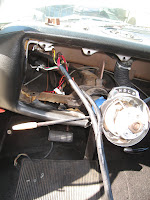
It was actually a little bit of work to get it through there by myself. I had uncoiled the new harness and stretched it out as far as I could, and the different circuit branches kept getting hung up on things (the seatback, the turn signal stalk, the steering column Z-bar) as I pulled it through. Finally, though, I got it all the way through and began changing connections, starting with the alternator wires (farthest point of the harness) and being careful to bend the bundle the same as the old ones to fit into the wire clips around the radiator support. Notice in the pics below that there are several clips at strategic locations to guide the wire bundle around the radiator, under the horn mounting positions, and elsewhere in the engine compartment.


Notice also that there are a few leads in the harness that are not connected. There are usually a few of these in any car; in my case, the low-tone horn and the overdrive relay. Loose wire leads are a big peeve of mine. They can get in moving parts, or arc to ground unexpectedly, so I always tie-wrap them to the main bundle, as you can see above.

I had left the engine half of the old harness in place and simply substituted the new connectors for the old at each connection along the way. Sure, you could use the wiring diagram, but why not make it easy?

Also, here's a plug for some good stuff. Caig Labs in Poway, California (right up the road from me) makes a product called DeoxIT. This stuff is magic! If you spray it on old electrical connectors, it will remove oxidation within minutes; the junk just wipes right off, without harming the connectors themselves. There's also DeoxIT Gold, which is a lubricant/connection enhancer that you spray on afterward. Lest you call BS on this, let me tell you that I've measured connection resistance myself in connectors with and without DeoxiIT Gold, and it does indeed seriously lower the resistance. You can get it at almost any Radio Shack, or Frys, or like stores. I used this on every connection under the hood, and on the dash switches as well.

Also, just to make sure that the underhood connections stay moisture-free, I used a dab of dielectric grease on every connection point. This is the stuff the factory uses in all the booted connectors to keep connectors from corroding or absorbing water.

After finishing the engine compartment, Iwent into the cabin. First thing I figured I'd do was to bolt the new fuse/flasher block to the dash, since it really locates the rest of the harness bundle. In my Lark, the flasher panel shares a mounting position with the driver's side air vent control - the vent rod bracket bolts to the bottom of the dash frame, and the same screws hold the flasher bracket to the top of the frame. I had previously installed all the connections and fuses that live in it, so I began to screw it on -- and ran into my first bit of trouble. The flasher can was too big; it interfered with the vent rod. I had read the number off the old flasher and gotten a direct replacement from my NAPA, but a check of the manual revealed that it was, in fact, the wrong flasher. How did the old one fit in there without banging on the vent control? Well, my old flasher block was busted - one fuse connection was actually broken off and was being held in place by the fuse! I think that a PO probably put in a flasher they had on hand, and when it didn't fit, he just bent the bracket forward, breaking the board! Luckily, SASCO had NOS parts in stock, and I got one before they closed down.

NEVER TRUST THE P.O.! After a hasty trip to NAPA, I installed the correct flasher and proceeded. In the pic above, you can see the difference between what was on the car, and the correct (short) can.

After that, things went pretty well. I routed the new wire bundle over the steering column support and into the clip that holds it down, and separated the pigtails for the various switches and instruments into their approximate locations.

Let me point out that while most fuses in a Studebaker dashboard are inline in their respective circuits, there are two circuit breakers as well; one 20A breaker for the headlights and a 5A for the wipers. They are located at opposite ends of the instrument nacelle. The headlamp breaker is in a holder at the lower forward left corner of the panel (think: just above the hood release, but inside the dash structure) and the wiper breaker is in a like holder on the right side, attached to the steering column Z-bar. While they are situated in such a way that you wouldn't know where to look for them if you didn't know where to look for them (figure that out!), once you know where they are, you can get to them pretty easily from below.


While the instruments were out, I took the opportunity to remove my defogger vent heads and attach new flexible ducting obtained from Studebaker International. It was nearly impossible to get the new ducts mounted properly while the vents were in the dash, but they're held on with just two small screws each. I snugged the new hose on the inlets and secured them with Zip ties, then bolted them back up to the dash.

Next step was to start hooking up the gauges and switches. I set the new guage bezel on top of the steering column and started hooking up switch wires according to the wiring chart. This is a bit tricky; first, the shift lever interferes with the bezel's direct entry to the dash; even in the "Reverse" position, you have the heater/defogger control cables attached to their levers, which must be guided through the dash structure. While these are flexible, the OEM cables are spiral-wound metal, not plastic-sheathed, and can be bent if you're careless. In fact, I managed to bend the rightmost cable but was lucky enough to try the controls while the cables were still accessible through the gauge holes, and I straightened it so that it could slide without hanging up. Also, the metal bezel can scrape up the top of the steering column pretty good; I wound blue painter's tape around the column to protect it during this operation.

After the switch and the Fuel/Temp/Oil/Charge gauge connections were made, I pushed the bezel into the dash and started installing the six #10-24 3/8" self-tapping screws that hold it in. How do I know what size they are? Because I lost one, somehow, in the dash structure. One minute it was in the socket, the next it was nowhere to be found - nowhere! This prompted a trip to Ace hardware, since I had also found a screw missing in the bracket that holds the parking brake to the dash. Ace only had 1/2" screws, so I had to shorten one to 3/8" using my Dremel.

The hardest connection to make to the left-most gauge is the oil pressure line. The gauge is a direct-reading mechanical type, so the line is a hard copper tube that attaches to the engine with a flexible coupkling, then comes through the dash and ends in a miniature double-flare that screws into a fitting on the back of the gauge. Try as I might, working through the clock and speedo holes, that danged line did not want to screw into its fitting. At this point, I'd been at it for 6 hours and decided to call it a day.

On Sunday afternoon, after a good lunch, I decided to try it again. I got into a better position ("better" being a relative term) with the help of a pillow and Mini-Mag and succeeded in getting the oil line installed, working from below. Let me tell you, it was about as comfortable as flying coach on a Delta flight!


After that, it took about 5 minutes to set the speedo in place and hook up its drive cable and the leads for the directional and high-beam indicators. Time to hook up the battery!

I crossed my fingers and put the battery cables on. Nothing sparked or leaked smoke, so I said a quick "thank you" prayer and put the key in the ignition, at which my first mistake became apparent -- the windshield wipers came on with the key; I'd installed the leads to the switch backward.

But that was no big deal. Now for the high-wattage stuff: the headlights, taillights, beam selector switch, turn signals, instrument lights. Success! All worked nicely.

I turned the key to "start" and the engine fired up after a couple of cranks - Success! But the key was turned right off as I saw, through the open hood, smoke coming from the new coil resistor I'd installed. (Studebakers West can't get the resistance wire the factory used to supply power to the coil when the key is in the "run" position, so they give you an old-style external resistor that mounts to the coil bracket.) I quickly went and pulled the cables off the battery, then checked the resistor. But the wires were cool; the smoke was coming from the resistor coil itself. I guess brand new ones just smoke a little when the current first hits them. I put the cables back on the battery and fired the engine again - sweet!

There were only a couple of small errors to fix, such as the connections to the wiper switch and the ammeter, which I apparently wired in reverse - the needle went to the "Charge" side of center when I turned the headlights on, and swung to "Discharge" when I revved the engine! But those were easy fixes, and I corrected them after work yesterday.

The one thing left to figure out is the behavior of the headlight/parking light switch. The parking lamp position of the switch doesn't seem to work - no lights on the corners in the center position, but they come on with the headlights like they're supposed to. It's possible that the switch is work out and not working right - we'll see.

The only part of the harness left to install is the back half that feeds the tail and reverse lights, but there's no hurry for this, as all those wires are in relatively good shape.  At least I don't have to worry about nightmares like the scene at left anymore!

Next project is getting the new master cylinder and brake lines installed, and she's on the road!

Click here for the final part of the wiring installation series >>

Labels: , , ,

Wednesday, September 16, 2009

Wiring Harness Replacement, Day 1.

Well, I hadn't really planned on this job, but some things just demand to get done all on their own.


After putting the new distributor in Barney and getting him going, I was futzing around inside and was, once again, taken by the rat's nest of messed-up wiring under the dashboard. I knew that the wiring harness was going to need replacement soon after buying him; there was a bundle of wires hanging out from beneath the ignition switch that had bare ends with tape over them! And there were other things, like the fact that the heater blower circuit was open... the headlight beam selector was bypassed... the horn circuit had shorted out and melted the harness for about a foot... and the fuse block was literally broken in half.

And the thought hit me: why wait? Why not do it now, before the car's back on the road? Because once I'm driving it, I'm not going to want to take it down to do this job. Also, I don't want to be standing next to a smoldering heap of metal on the side of the road somewhere because I didn't do it!

Luckily, I'd ordered a new OEM-style harness from Studebakers West in Redwood City. Mr. Biggs on the SDC Forum had told me early on that SW were the ones to go to, since they make their own harnesses from factory loom charts. And let me say, it's a beautiful piece of work!

So, after talking it over with my wife, I plunged in last Sunday. I'd sought advice on the Forum about how best to do the job; some told me I should drop the steering column and remove the entire dashboard. But a couple of guys told me I could do it by removing just the steering wheel and the gauge cluster, and working through the gauge pod opening. Since I already had all of the gauge pods removed, I decided on this course of action.

One of the guys on the Forum told me that no matter how long I thought the job would take - it would take about double that! All I can say is, was he ever right :)


So, Saturday night I laid out my new harness on the living room floor. I'd already gone through it with a continuity tester and identified the wires, tagging them with P-Touch labels. (Yes, that's anal-retentive. I believe in being prepared.)

Just to make sure, I went through with the wiring diagram again and was glad I had - I found a couple of mis-labeled wires (one, meant for the overdrive solenoid, was labelled "To coil positive"! That would not have worked.)

By the way, if you need a wiring diagram for your car, you'll find the ones in the Shop Manual fairly useless. Go to Chuck Collins' archive instead and find the one for your car. Trust me, you need this!


You'll find a thick rubber grommet where the harness passes through the firewall. This is installed by slipping it over the engine-compartment wires and fitting into the firewall hole. The wires must be fed through the firewall from the passenger compartment; the grommet is then installed from the engine side. This means you cannot pre-install the grommet before the wires go in -- something I had to learn the hard way.


I've been collecting parts for a while, so doing the harness also means replacing the nasty old painted gauge surround with the nice chromed one I've had waiting. Seems that, along with other austerity measures, Standard gauge pods were painted silver instead of chromed! My new one won't be "correct", but it will look much nicer. I also unearthed the new headlight switch, instrument light dimmer, heater control cables and other bits and pieces I'd assembled to replace what was broken, worn or just plain old.

Before diving in, I went around the car with the digital camera and took still photos of every wiring connection, plus video of everything with narration - just in case I mess up somewhere (cross your fingers!).


Finally it was time to get into the dash, starting with removal of the crappy Grant GT steering wheel. Why is it every two-bit hot-rodder wannabe has to put one of these things on? Getting the wheel and mounting hub off instantly revealed one reason the horn never worked: about a foot of thin wire wrapped around the turn signal's cancel switch, accompanied by two crimp-on butt connectors. Hopefully, the real horn wire is still in the column and can be retrieved, but I won't know until I pull the Grant adapter and switch collar.


With the wheel out of the way, I could get into the gauge pod and access the six screws that hold the bezel to the dashboard. There are four across the top and two on the bottom. Working through the mounting holes for the instruments, they were easy to get to using a mini-ratchet and 1/4" socket. Once these are out, the bezel is loose - almost. I found two trim screws on the bottom of the dash pad, adjacent to the steering column, that must come out. Then, the bezel is free to pull forward. I put some painter's tape on top of the steering column to avoid morking the paint up. I also unscrewed the ignition switch and four rocker switches and let them remain with the harness so I could photograph their connections.


Woo hoo! I could finally get to the interior of the dash. And boy, what a mess! Wires that went nowhere. Pulled-apart butt crimps with bare ends. More melted wires and electrical tape. Unprotected power taps coming off the main battery feed. Made me really glad I decided to do this project now rather than waiting!

Studebakers have no fuse panel per se; inline fuses are scattered throughout the harness along with two circuit breakers (one for the headlights, one for the windshield wipers). You'll find the breakers at either side of the pod, clipped to the backside of the dashboard frame in little holders. Headlight breaker is 20 amps, wiper is 5 amps. Mine were both 15 amps (go figure).


At this point, I took time to document the connections to the fuse panel. Okay, flasher panel would be more accurate, since there are only two fuses on the board and the directional flasher can is mounted here too. Naturally, there were also some accessory power leads screwed on, none of which powered anything. One lead, a big white one with a black tracer, was so obscure that I took my knife and cut open the remaining plastic tape so I could find out exactly where it went!

I'd started working in the car at 11AM; it was now 6PM and I'd finally reached the place where I was ready to cut the old harness at the firewall. The plan, put forth by Mr. Biggs, was to cut the harness and leave the engine side attached, so I could thread the new harness through the hole and just swap the connectors, using the old ones as a guide.

So I went and got my wire nippers and began snicking through the bundle on the engine side of the firewall, one wire at a time. And AGAIN I became very glad I'd decided not to put this job off! It seems that the pesky horn wire meltdown, in addition to burning through the harness wrap, had also managed to scorch the thick main power lead that goes from the alternator to the ammeter.


So, after 7 hours, I finally got to pull the old harness free of the dash. It was a long, tiring day, but I'm really glad I did it, and I have a good feeling that with all the research and pre-planning I've done, the new harness will go in pretty easily. It'll have to wait for this coming weekend, but that gives me time to get a few odds and ends - fuses, bulbs, breakers and sundry other goodies.
In addition, I've sent my clock off to get rebuilt by a pro, so when it comes back next week it'll be ready to go in that hole in the middle of the dash where the blanking plate was!

Labels: , , ,