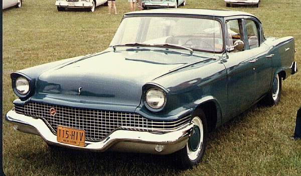
The Studeblogger

Wednesday, November 25, 2009

I'm thankful for new brakes!


It's Thanksgiving, and I have much to be grateful for - my beautiful wife of 22 years, my son Reed who isn't too much of a wiseacre too much of the time, my job, and good friends and family. And I thank God for all these things.

But today I'm thankful for one more thing - brand new front brake drums and hubs from Chuck Collins, which came with the FedEx man around lunchtime. Along with the new wheel bearings and oil seals I'd squirreled away, these will go to Vista Brake next week -- hopefully, along with the set of used rear drums that are en route from Bob Peterson. Once Bryan gets these, Barney will be on the road again. Hmmm, I can hear Willie Nelson in my head...!

You can find Chuck Collins' Studebaker Parts Online at:

StudebakerParts.Com
2410 W. Freeway Ln.
Phoenix AZ 85021
602-995-5311

And if you're looking for parts from Bob Peterson:

C & B Studebakers
Castro Valley, CA
510-266-2522

Happy Thanksgiving!

Labels: , , ,

Monday, November 16, 2009

And off we go.


This morning Barney moved under his own power... up the ramp of a flat-bed tow truck :) It was a planned excursion, though - the brakes have to be gone through before I'll consider taking him onto the open road..

So, for the first time since August of 2006, he's out of our driveway. With the help of my wife, I made a three-point turn in our driveway and faced him out to the world, then called for a tow using my Hagerty Plus membership. Hagerty Plus is like AAA for collector cars; you get up to three free 10-mile flatbed tows per year.


So I called, and in about 45 minutes S&R was at the door, and we loaded Barney onto his truck. I actually drove it onto the flatbed, which was a bit tense because I had to really get on the gas to move him up the ramp - the first time I've really put power to the rear wheels in gear. Because he hasn't been driven so long, the tires are pretty shiny and I spun 'em a little at the very end, which caused the car to slide sideways a bit. The driver decided at that point to call it good and chained her down for the ride.


We took kind of the long way 'round getting there, but arrived at Vista Brake without incident about half-an-hour later (me keeping a respectful distance behind the truck in case anything unpleasant should occur).

I can't recommend Vista Brake highly enough. If you're in North San Diego County and need brakes, alignment, suspension or other work done, they are the place to go. I've known owner Brian Dornan for years; he's worked on all my cars (and his dad before him) since the 1980s - my '67 Pontiac, my long-lost Dodge Rampage, my wife's Honda Pilot, etc. etc. He and his crew are excellent mechanics who can take care of just about everything; while I was there he showed me a fat-fendered black '51 Mercury 4-door sedan that they're finishing up full brake and suspension work on - very smooth car with a big-block Chevy under the hood ;)

Brian will take care of stuff I can't do at home - pulling and packing the rear axle and wheel bearings, front-end alignment, new brake lines and hoses front to rear, and a conversion from single-circuit master cylinder to dual-circuit (which most '63 Studebakers already had, except for the bare bones cheapo Standard model, which is what Barney is.

Oh, and he'll also fix one of my boo-boos - installing the A-arm jounce bumpers in the front suspension, which I inadvertently left off during the rebuild. Stand by for details!


Sunday, November 15, 2009

Adventures in shock-land.

Tomorrow Barney goes to the brake shop for new binders and an alignment, so I wanted to do a job I'd put off for over a year - changing out the rear shock absorbers. I wanted this done before the alignment, since the angle of the front wheels will change along with the angle of the rear end.

The reason I'd put it off so long is that, to be perfectly blunt, changing the rears is a royal bitch. The upper shock mounts are located in a frame cross-member that lies in the highest part of the floor pan, the kickup over the rear axle.


I took the photo above laying underneath the rear axle, looking up at the left upper shock  mount. There wasn't really enough clearance to get a good angle for the photo - so you can imagine the working space! The through-bolt's head goes in from the front of the car; the self-locking nut is in behind the flange on the rear, in a tiny recessed space between the cross-member flange and the trunk floor - just enough space for a box-end wrench, but not for a socket+ratchet combo. With the exhaust pipe in the exact center of the working area, getting your arms in there to hold the nut and turn the bolt is kind of like driving a '75 Buick through a slalom course after a night of heavy drinking,


Caution: to do this at home, you need to jack up the rear wheels for clearance. This means that the parking brake is rendered useless. Be safe - use wheel chocks before and after both front wheels, and jack stands under the rear axle under the springs. I also leave the floor jack under the pumpkin as well for good measure - better safe than sorry. Don't take short cuts with your life!


It took me about an hour and a half of sweating, spitting and being drowned in a shower of rust flakes from the exhaust pipes to get the left shock off. In the process, I managed to run over my own shoulder with my creeper and raise a bruise the size of Catalina Island (ouch).

The old shocks were still operable, but obviously tired. The replacements were the same exact Gabriels that came off the car!


The new shock went in without much effort, since I now knew where everything was. I chased the threads on the mounting bolt just to clean them up, then proceeded to install the shock. The only hang-up was with my torque wrench: the bolt had to be torqued to 45 foot-pounds, and my 3/8" wrench with the 12" handle doesn't go that high. So I had to use the 1/2" drive, with the two-foot handle... which meant that I had just enough angle to turn the bolt one click with each swing. Getting it to torque was an interminable process, but I did it.

The right shock went much more smoothly, taking only a half-hour to R&R (albeit with another gallon of rust-flakes dislodged).

Once the shocks are in and the nut on the bottom stud is tightened up, be sure to add the locking nut. These are not included in the shock absorber hardware package, and the Shop Manual decrees the use of PAL nuts. Luckily I had some left from the front shock installation, which I'd gotten online from Aircraft Spruce.


Just snug the flat side up against the stud nut and they're locked in place, yet still easy to remove! Pretty smooth.

After all was said and done, it wasn't that bad, but would certainly be a lot better using a hoist :)  And, even with the tired old leaf springs in the back end, the car sits about 2" higher!


Labels: , , ,

Thank you!


The guys over at Amazon.com's Car Lust blog listed The Studeblogger as one of their favorite car blogs! Aw shucks... I'm blushin' :)

Thanks guys!

Labels:

Hey... your head is loose!

While I've been occasionally accused of not having my head screwed on tight enough ;) I'm talking about the bolts on your engine's heads in this case.

StudeKen (Ken Pyle, who rebuilt my 259) reminded me that the head bolts needed to be re-torqued after the engine had been restarted and run a bit, which mine now has. So, yesterday being a beautiful 72 degrees here in SoCal, I decided on a little StudeWrenching in preparation for road-worthiness.

First step is pulling the valve covers. If you're a GM guy like I was, you're probably used to a lot of hold-down bolts around the base of the covers, as seen below on my '67 Pontiac. Some other brands have quite a lot more bolts!


In contrast, Studebaker valve covers are easily removed without fumbling around by just unscrewing the two bolts in the center of the valve covers (4 bolts on older models):


The studs protrude through the valve cover through rubber seals, easily available from SI and other vendors. Just undo them, and pull the valve cover off (after removing the spark plug wires, of course). The valve covers seal to the heads using re-usable, soft neoprene rubber gaskets, and they take a little pulling to get loose; don't be shy, just grab the oil filler tube and give it a gentle yank.


With the valve train exposed, you'll have easy access to all the head bolts. There are 18 of them, as shown in the figure below, taken from the factory Shop Manual:


The manual specifies 55-65 lbs.-ft. of torque for each bolt. I usually split the difference, and so set my wrench right in the middle at 60 pounds for this operation. Note that the diagram shows a specific sequence for tightening the bolts; although this is specified for head installation, I used it for the re-torqueing operation as well (better safe than sorry!) Note that the 5 center bolts under the valve cover get torqued twice.

I was surprised at how loose a few of these bolts had gotten with just some running-in-place in my driveway! They all broke loose with the first pull of the wrench, on average took a quarter turn before the wrench clicked to indicate torque. A couple of them took nearly a full turn, specifically the two furthest forward adjacent to the water manifold.


I used a 12" extension to get the proper leverage on the torque wrench for most of the bolts, but a couple - those furthest toward the firewall - needed a shorter extension to clear certain obstacles. On the passenger side, the flange for the heater plenum interfered; on the driver's side, the steering column forced using the 6" extension. I also had to shift the transmission's column shifter from Park to Reverse in order to drop the shifter linkage out of the way.


After you're done, the valve covers go back on easily. In the photo above, you can see the rubber seal iin its channel around the rim of the valve cover; make sure it's seated properly and not dropping loose, otherwise it could be cut by the interior flange and seal improperly - and there's nothing worse than engine oil dribbling onto your hot exhaust manifold while you drive!

The Stude shop manual calls for 14-20 inch-lbs. (!) of torque for the valve cover nuts. Now, maybe back in the day everyone had tools calibrated in inch-lbs. just lying all over the place, but here in the 21st century you're more likely to find a dinosaur bone in your backyard than such a device at your local Sears.
14 inch-lbs. is not a lot of torque, so I just used a nut driver to tighten the nuts hand-tight, which is all the neoprene seals really need.

All done! Put the spark plug wires back where they belong and DON'T forget to reattach the throttle return spring to the wire clip welded to the driver's side valve cover.

Labels: , , ,

Friday, November 13, 2009

Studebaker Steering Box Info.

Studebakers used a few different models of steering gearbox over the years, from primarily two sources: Ross and Saginaw.The Ross boxes were cam-and-lever gears that were used throughout the 1950s and into the 60s on almost all Studebaker cars and trucks.Saginaw boxes were more modern recirculating-ball types used on some 50's Studes and post-63 Lark-types. Most people agree that the Saginaw boxes have less steering effort and are easier to repair.

Anyway, there's an easy way to tell which kind of steering gear your Studebaker has, as explained by SDC Technical Editor Bob Palma on the SDC Forum:
To determine if you have a Ross Box, see what size wrench is needed to remove the square pipe plug at the check/fill hole on top of the box. If the pipe plug requires a 3/8" or 7/16" wrench, it is a Ross box. If the plug is near the very top of the box and requires a 1/2" or 9/16" wrench, it is a Saginaw unit (thank goodness!)

Why does it matter? Primarily because the two different types of manual units take two different types of lubrication.


Left: Ross steering box. Right: Saginaw box.


The Saginaw boxes are easy to lube: they take standard chassis grease. You can literally pull the plug and pump in a few squeezes of chassis lube from your grease gun to top them off. The Ross boxes, however, take an 80w or 90w gear oil with EP (ex/treme pressure) additives; Kendall 999 was the preferred grease, but Kendall is no longer around. So, what to use?

Studebaker International to the rescue, with p/n 801651 Semi-Fluid Steering Grease. This is heavy stuff that can also be used as assembly lubricant when you're repairing a Ross or Saginaw box, or to refill a Saginaw after service in lieu of the special S-P steering lube that's long out of production.

Oh, and Jeff Tangemann of Lincoln, Nebraska writes that "a steering shaft out of a circa 68 Chevy truck will fit in a Lark Saginaw steering box." Good to know!

Labels: ,

Monday, November 09, 2009

Stop and go, or go and stop?

Good news: Barney might be back on the road by the end of this week! I've made an appointment with my buddy Brian at Vista Brake to bring him in for a new master cylinder, brake lines and hoses and a front-end alignment. Once that's done, he'll be back on the road again.

I don't mind telling you, I can hardly wait! My goal is to drive him to the November meeting of the San Diego SDC Chapter, which will be held just down the road from me at the Antique Steam Engine Museum in Vista. Wish us luck!

Labels:

Love that Lark! A family friend comes home.

Cars are so much a part of American life that almost everyone has a fond memory of a favorite ride. In this case, a car sold new 50 years ago by a Studebaker salesman - to his own grandfather, no less - has come back home to the man who made the sale.

Check out this great article from the November 7th Wichita Eagle and just try not to think of your favorite automobile...

Labels:

Monday, October 19, 2009

Lark Heater rebuild, Part 3: Installation

In Part 1, we yanked the old heater from the car. In Part 2, we made it all pretty again. In Part 3, we'll tackle putting all the disparate parts back together and making a functioning system again.

As the diagram shows, there are quite a few parts that have to go together - more little bitty ones than you'd generally expect. Luckily, as mentioned in an earlier post, most everything essential is available new from Studebaker vendors, even previously hard-to-find things like the Ranco water control valves that invariably wear out and leak.
 
First things first: Assemble all your bits. Here you can see all the stuff I've collected that make up the Lark's heating system: blower and core housing assembly, core gasket, newly-rebuilt heater core, refurbished heater/diverter box, molded coolant supply and return hoses, firewall hose grommets and Ranco valve + mounting bracket.

Before beginning installation, take a moment to lubricate your heater control cables. There are three; one that goes to the water control valve, one to the defroster mode flapper in the heater box, and a third to the air control flapper, also in the heater box. Studebaker used coil-wrapped control cables, so they are easily lubricated. I drenched mine liberally using a spray silicone lube.

The first item to go back in is the core/blower assembly, but first we have to reunite the core with its case.

I had my core rebuilt by what I think is the last old-school full-service radiator shop in North San Diego County, S&S Radiator King in Oceanside. S&S has been at it over 30 years, and they can fix or fab just about anything. I took my old core to them for testing and they confirmed that it was dead. "We'd solder one hole, and another would open up," said Mike, the owner. They searched around for a new core, but that size isn't made anymore. They scared up one that was about a quarter inch narrower, but still fit the tanks, and my heater was back among the living.

When I disassembled the core initially, I found that the factory used a generous glob of plumber's putty in each corner to keep the core from vibrating around in its case, so I did the same. I also found a small, triangular rubber bit that was placed in a crevice in one of the tanks; I don't know why it was there, but I saved it and replaced it.

Once the core was seated back in its case and the two mounting screws secured it to the flange, it was ready to re-mount under the dash.

The core is a very tight fit in the dash opening, and the mounting studs affixed to the dash are at the extreme corners of their mounting positions, so the core case must go onto the studs absolutely straight in order to make it up into the hole correctly. Don't forget to place the foam sealing gasket around the core before beginning the reassembly. I didn't use any sealer or caulk to hold the gasket on; bolting it into place is all the sealing it needs.

The core is held on by four nuts with anti-shake shoulders, like the ones shown at the right. You've probably already seen that the black ground lead from the blower motor ends in a ring terminal; it needs to be placed between the core case and one of these washers to complete the blower motor power circuit. Tuck the other two leads out of the way for a moment.

Now that the core and blower are reinstalled, we can mount the Ranco water control valve back under the dash. On earlier cars, this valve was mounted in the engine room on the firewall, but ours is in much closer proximity to the core and easier to service and install. Note the capillary tube that senses the ambient temperature; this needs to be coiled and located on top of the valve. I wound mine carefully around the handle of a screwdriver. The bracket screws to the lip on the underside of the dash with two big, honkin' sheet metal screws. It's best to connect the control cable to the valve before mounting it, since the tab that the cable screws to is harder to access with the valve in place.

Here you can see the relationship of the inlet and outlet nipples on the core and water valve, now that both have been mounted in the car:


What you can't see in the photo above are the holes in the firewall through which the heater hoses enter the cabin. That's right -- they're behind the blower case. There's enough room to get them by the case and onto their respective nipples, but only just.

It's time to start connecting hoses. The factory shop manual recommends using gasket shellac to paint the nipples with; not only will this lube the metal and make it easier to get the hoses on, but it will set up quickly and seal any gaps between hose and pipe, preventing leaks. I got a bottle of ol' skool Indian Head gasket shellac from my friendly local NAPA, where they've gotten to know me on sight since Barney arrived :) It works as advertised: paint the pipe, slip on the hose and tighten the clamp - you're done.

The factory used spring wire hose clamps, by the way, but I hate those things, so I use tower clamps instead, available at any auto parts store.

Although the long hoses with the molded ends that run from the engine into the cabin are available from Studebaker International, the short molded elbow that connects the water valve outlet to the heater core inlet is not. I took the old elbow to my NAPA and, bless their hearts, they picked a molded hose out of their parts bin that filled the bill. (It's a lot closer in dimension to the original than the photo makes it look.) It's NAPA part #11658, in case you're in need of one.

As the Body Manual diagram shows, the straight outlet on the water valve connects to the short pipe on the heater core, using the molded elbow shown above. Once that's connected, it's time to connect the two long hoses from the engine.

The hoses need something to protect them from being cut apart by the firewall, so there are rubber grommets that perform that function, again available from all the usual sources.

I spent a while figuring out how to get the grommets and hoses mounted in the car, and on my first attempt, I tried putting them in their firewall holes and feeding the hoses through them. Wrong move; I should have known that the friction between the rubber parts would prevent this from working. And once installed, the grommets contract a bit too - there was no way this method would work.

I realized that I'd have to slide the grommets on the hoses, feed the hoses through the firewall (one at a time) and then finesse the grommets into place. As you can see, one lip of the grommet is split so that it can compress enough to fit through the sheet metal and grip the other side. Once you've got it started in the hole, you can use a wide screwdriver blade around the perimeter to ease it into position. Or, perhaps, a piece of twine in the mounting groove to install it like you would a car window. (I used the screwdriver.)

Be sure to secure the two hoses to the fender using the strap just behind the alternator. If yours is missing, you can fabricate one or get one used from Stude vendors. On V8 cars like mine, the shorter of the two hoses runs from the elbow on the top of the water manifold to the water valve inlet; the lower hose runs from the lower nipple on the manifold to the long pipe on the heater core.

If you have a 6-cylinder car, the top hose runs to the elbow at the rear of the head and the bottom hose goes to the nipple near the water pump.

When the connections are complete, the core and valve look like this:


The next step is to install the diverter box and connect its control cables. Installing the diverter box is pretty simple; just slip the end over the blower outlet and raise the other end, then secure it to the bracket on the dash using the big screw that held it in. Don't forget to include the wiring harness clip; tuck the wire bundle that goes to the neutral safety and directional switch into it and you're done.

Now for the control cables. Slip them onto the actuator arms for the fresh air control and defroster diverter, and secure them to the metal tabs using the little squiggly spring clips discussed previously. The tang goes into the little hole in the mounting tab, and the other end snaps over the end of the tab These clips are tough to get on by hand, especially if you bought new ones; the easiest way to do it is with a pair of pliers to snap the end, as you can see in the photo below:


After the cables are on, you can connect the defroster ducts to the outlets on the diverter box. As I did with the other end, I used Zip ties to make sure the hoses don't blow off or come loose. I also used a Zip tie to secure the longest hose to the edge of the dash using one of the convenient factory holes. The factory used a metal strap of some kind to do this, but it's no longer available and the Zip tie is just as good.


There's just one thing wrong with this picture: after I connected the blower leads to the dash harness, there was a lot of extra wire. There was no way I was going to leave it like that. More modern tech to the rescue: these spiffy little self-adhesive cable locks I found in the automotive department at Wal-Mart. A couple of these stuck to the bottom of the diverter box and the mess was tidied.


Only one thing left to do: install the screen filter that keeps leaves and other debris from getting into and plugging the heater core. This is a woven metal mesh that slips into the firewall from the engine compartment, and has a rubber seal on the edge that keeps fumes and moisture out. These are available from Studebaker International. My original was shredded thanks to the rodent tenant, so I got a new one.


Congratulations! The heater is now functional again, ready to make your Stude comfy on those winter outings. It's one of the few times when plenty of hot air is a good thing :)

Labels: , , ,

Sunday, October 18, 2009

Lark Heater rebuild, Part 2: Refurbishment

With the heater system removed from the car and disassembled, you can start refurbishing the parts that are salvageable and hunting down the replaceable parts (hoses, clips, cables, etc.).


 Here's yet another great reason to get a copy of your Shop and Parts manuals on CD-ROM: you can print out individual pages. The one above shows all the bits that go into the '62 - '63 Climatizer system. Almost all of the larger parts (fan case, diverter box) are available used if yours are missing or damaged beyond repair; almost all of the small parts (cables and cable clips, fan cage, molded hoses, water valve, heater core, defroster duct hoses) are available new from Studebaker International or other Stude vendors.

A lot of my larger parts were rusty thanks to the leaky core and valve dripping antifreeze all over them for - well, probably years. I decided that this would be a good time to try using electrolytic rust removal, a process that uses electricity instead of blasting or wire-wheeling to get rid of the corrosion on steel  parts. You can read about the process in detail at The Stovebolt Forum, but here's the process in a nutshell: Find a plastic container, fill it with water, and add a tablespoon of Arm & Hammer baking soda for every gallon. Stick a piece of rebar or other sacrificial iron or steel stock in the water to use as an electrode; your rusty part becomes the anode. Submerge your rusty part in the water and connect your battery charger's negative cable to it; connect the positive cable to the electrode bar and switch it on - the more amps, the better. (One SDC Forum member told me confidentially that he'd derusted an entire engine block this way using a stainless tank and a welding power supply. I do not recommend or endorse this method!) Don't submerge your clamps, or they'll get eaten away! I decided to try this on the blower fan, which had surface rust all over it. Here's how it looked just after switching on the juice:


And here's how it looked about four hours later:


This nasty muck is all the rust that's been electrically removed from your part! Don't worry, it's not toxic, just fugly. After about a day, here's what came out of the soup:


It may not look very pretty, but it's no longer rusty :) That black coating is what's left behind by the process in place of the rust; a swipe with a kitchen Scotchbrite pad removes it and exposes shiny metal that can be primed and painted. I used this method on all of the blower case parts. The top of the case that holds the core started out like this:


...and came out like this. One of the side benefits of the process is that it loosens most paint, so it comes right off. I buffed the clean metal with a Nyalox wheel from Divine Brothers.


After the buff, the pieces were so pretty I was almost tempted to clearcoat them and leave them this way :) But everything got a nice coat of Rustoleum primer and gloss black and were set aside to cure.


While all this cleaning and painting was going on, I was ordering parts from SASCO and SI: hoses, a new blower motor, and other small but essential parts. Once they arrived, it was time to start reassembling the cleaned and painted parts. To attach the blower motor to the case, place the gasket over the long machine screws installed in the motor case and place the case over the threads. New locknuts on the blower side hold it all together; I put a little Loctite on the threads to make sure the blower vibration doesn't loosen the assembly. Make sure you orient the motor so that the power leads exit toward the blower case outlet.

Next, push the fan cage onto the motor shaft. Use care here; you don't want to bend the fan off-center, so don't push on the rim - push only on the hub. A socket on an extension handle can be used to get the hub down on the the shaft.


Leave about 3/16" of shaft exposed for the spring clip that goes on top to keep the fan from leaving the shaft at speed. New ones are round versus rectangular originals, but functionally they're the same. Use the socket to slide it tight against the fan hub.

After the blower fan is reinstalled, you can reassemble the blower case. Since a previous owner had used the wrong screws, I re-tapped the holes and installed the correct screws to hold the case together. Set the assembly aside; it's time to work on the air diverter box.


As mentioned in the previous installment, the fiberboard diverter flaps inside the box that control fresh air flow and heater/defroster mode had long ago lost the rubber sheets stapled to them. This meant I would have to disassemble the box, since there is no way to access both flaps from the outside. I also decided to use something a little more durable than rubber sheet to re-surface them.

Chances are you will need to perform this operation as well, so you'll need to remove the old-school rivets that hold the formed cardboard top onto the molded plastic bottom. It's that old-time thermo-plastic with the fibers impregnated to give it strength. But it's still soft plastic, and I didn't want to drill out the rivets because they'd spin and enlarge the rivet holes, so I used needle-nose pliers to bend up the tabs and remove them.

Once the top's off, the flappers can be removed and re-surfaced. I got two 8.5 x 11" sheets of black felt from Michael's; one with self-adhesive backing and the other plain, and laminated them together to obtain the correct thickness.

The residue left on the rectangular piece indicated that the original covering wrapped around the end of the piece opposite the hinge rod. After cutting the felt sheet to the proper size, I glued it to the hardboard using a liberal coating of E-6000 cement. I did the same to the round flapper, applying the felt to both sides.


Note that there is a small washer at the top of the shaft on the rectangular flapper. Don't lose this! It needs to be on the shaft when you reinstall it so that the flapper will move smoothly and stay at the correct height.

As mentioned before, the top of the box is made of pressed cardboard; mine looked a bit tatty. On the advice of a poster on the SDC Forum, I brushed it with a mixture of carpenter's glue and water. Not only did this visually rejuvenate the aged cardboard, it also stiffened it and made it water-resistant (just in case the heater ever decides to leak again). The results were really spectacular, and after the glue wash dried it was time to re-assemble the halves of the box.


Start by locating the diverter flaps in their holes in the bottom of the box. Note that the arm on the round flapper is pointing down. After the flappers are located, the top can go back on.

I tried a couple of things to fasten the top back on; at first I used plastic pop-rivets but they didn't grip - they loosened right up. Then I tried an aluminum rivet, but it took too much force to tighten and I was afraid of cracking the plastic. I wound up using #6 machine screws with lock-nuts to secure the unit; not correct, but not damaging. And, if I ever need to open it up again, it'll be easy to do.


Now that the blower and diverter box are refurbed and reassembled, we're ready to re-install them in the car. Stay tuned for Part 3!

Labels: , , ,

Lark Heater rebuild, Part 1: Disassembly

Here we begin a three-part series on how to R&R your non-functional Studebaker Lark Climatizer (Studebaker's term for their temperature-maintaining heating system). There are of course variances between years, but your Shop and Parts manuals (you do own them, right? If not, get them from Studebaker International or one of the other Stude vendors, either printed or on CD-ROM) have year-specific exploded diagrams and parts lists. Since I have a '63, this series will be specific to '62 - '63 Larks, but the procedures are pretty much the same for all years.

Barney's heater didn't work from the day I bought him. The PO had disconnected the heater hoses because the water control valve had failed, then leaked and frozen in a partly-on position; the continuous drip had also corroded the control cables and frozen one of them solid. Besides that, the heater fan would not operate; not only had the hacked wiring harness caused a power feed to the blower circuit to be disrupted, the core had leaked and let water into the fan motor itself and corroded the bearings. So nearly every part of the heater system would need to be replaced or refurbished.

The pic above shows the blower case and core assembly, which is located in the cabin underneath the passenger's side of the dashboard. On earlier Lark models, the core and blower are located in the engine compartment, on the passenger's side fender, and fresh air is fed through a hose connected to the vents inboard of the headlights. With the advent of the four-lamp system in 1961, the core and blower were relocated inside the cabin, but the water valve was still in the engine compartment on the firewall. In 1962, the valve was mounted under the dash as well, which means when they leak (not if, when), you'll know it immediately. Ranco valves can now be obtained again after a long time out of production; I obtained a used one from eBay and had it ready to go in.

The first order of business was to remove the old core and blower assembly. This isn't too hard, as it's held into the dash by four nuts and studs. the top of my core had been the nesting place for a rodent at one point, and though I'd vacuumed out as much of its bedding as I could through the filter slot in the engine room, there was still a lot of organic matter on top when it finally came out, as you can see here. The core is a tight fit in its hole, and even once the nuts are off the studs it requires some finesse to get it out, especially since clearance with the firewall is minimal.

In my Lark, the old core was sealed to the dash opening with some sort of dum-dum or black caulk; either that or the original rubber seal had simply turned into goo after 45 years. Either way, it was sticky and reluctant to let go, but once it was broken, the assembly came down the studs and was sitting in the floor of the car. Since the motor was seized and the wiring harness about to come out, I nipped the motor's power leads and the core was free.


As you can see, there are three major three major pieces to the heater/blower assembly: the heater core itself, the blower motor, and the fan case. The core is the first piece to remove; it's held onto the blower case with a sheet-metal screw on each side. Once removed, the core comes right out.

With the core removed, I found four pieces of ossified white crud in the four corners of the case. Careful inspection revealed these to be preshistoric plumber's putty, put there by some line worker decades ago to hold the core safely in its case.

I then disassembled the blower case by removing the short #6-22 machine screws that ring the clamshell's flange. Well, actually I had only one #6 screw - the rest had been replaced at some point by a motley assortment of wood screws and coarse sheet metal screws. Opening the case exposes the "squirrel cage" blower fan, which has to be removed before the screws that secure the motor to the case can be accessed.


With the fan exposed, I couldn't resist trying to make it spin, so I hooked the leads up to a 12-volt drill battery. At first, nothing happened, but after freeing it up by hand, the fan took off with a loud squealing of dry, seized bearings and I knew for sure that a new motor was needed. Luckily, they're easily available; I got mine from SASCO.

With the blower/core out of the car, the heater diverter box is held on with just one screw, a big one that also holds a clip that keeps the wiring harness from falling on the floor. It's a good idea to remove the control cables before taking out the screw; they're held on by small spring clips that clamp the cable's spring-wound sheath and keep it from moving as the actuator is moved.

If your clips are broken, bent, missing or go flying off to Never-Never land when you remove them, don't fret. Apparently AMC used these clips as well, and they are readily available from Studebaker vendors; they are part #1331825. Some models require just one; my Lark needs two and one was missing and was one of the new parts ordered from SI.

After removing the heater box, the defroster ducts are usually hanging free from the outlets. These hoses were originally made of black paper wrapped with a spring-coil substrate; mine deteriorated long ago and the inventive Previous Owner had fixed the problem by wrapping what was left with duct tape. The black paper then crumbled away entirely, leaving the ducts a sort of automotive fossil part. I discarded these archaeological objects and bought the new rubber ducting with nylon inner-spring sold by SI. The outlets themselves are pressed steel and are held on with a nut on each end, which (with the heater out of the car) were easily accessed with a socket and extension.


Working on the kitchen table, I cut the new hoses to fit using the old ones as templates, and secured them to the outlets using a method not available to Studebaker line-workers back in the day: Zip ties. Slipping the hose as far over the outlet necks as possible and tightening down the Zip ties secures them beyond any loosening, yet enables me to remove them down the road if needed. Since I had the instrument cluster out for the re-wiring project, it was even simpler to reinstall the re-hosed ducts, but it's not bad even with the cluster in as long as you have a good flashlight.

Now the that heater box was out, it was obvious that it would need refurbishing as well. Looking at the two air diverters (one to close off outside airflow, the other to select between heater and defroster mode), I could see that the rubber sheet that was originally stapled to their surfaces to facilitate sealing was long gone. Well, like I said - every part would need refurbishing!

The next installation will cover rebuilding and refurbing the various heater sub-systems. Stand by!

Labels: , , ,

Sunday, September 27, 2009

Wiring Harness Replacement, Day 4 - the finale!

This weekend I finished the wiring harness project, pulling out the old taillight harness and installing the new one. Everything is brand-new wire, from headlights to taillights.

As with the front harness, the rear wiring came from Studebakers West in Redwood City, California. Nice stuff, with OEM wire colors; a drop-in replacement for the original.

The factory harness was routed under the carpet next to the driver's side of the front seat, up under the rear quarter panel trim, over the rear wheel well and past the trunk divider, where it then clips to the driver's side of the trunk, near the trunk opening, and then to the left taillight, across to the gas gauge sender and finally the right taillight. It's really easy routing; all you have to do is follow the clips spot-welded to the body.

First thing was to pull up the carpet a little, which necessitated removing the driver's kick panel and door sill plate. That's where I found the first rust hole in the floor, right at the base of the A-pillar, where the floor meets the front wheelwell. Just a little hole, about 3/8", but I was sure hoping there wouldn't be any. Guess it's a Stude trademark though, so we'll deal with it.

I also had to pull the rear seat to route the wires into the trunk. The seat bottom lifts right out; the seat back hangs on two little hooks on the package-shelf cross brace, and is then secured to the floor with sheet-metal screws through two oblong loops on the bottom of the seatback. Undo those screws and the whole back lifts right out.

As long as I was in there, I pulled off the quarter panel trim and shot as much WD-40 into the window regulator as I could, freeing up the window, which had only been able to roll down about 4 inches.

In the trunk, the only thing that required cleaning up was the connection to the two license plate lamps, which had been butt-crimped to the harness connector. I nipped them off and crimped on some bullet connectors to plug into the new harness. Everything else was easy as pie.

I vacuumed up the detritus under the rear seat, which is when I found the other little hole in the floor - this one under a pile of dried dum-dum at the front corner of the rear wheel-well. This one was larger than the first; about the size of a quarter - I could easily see daylight and pavement through the hole. Some 200-MPH tape for the time being, but we'll have to address this, too.

That completed the job, and after reinstalling the seat and door trim, I bolted the Stupid Grant Steering Wheel â„¢ back to the column. She's really ready for the road now - all that really needs doing is the brakes - stand by for the next installment!

Labels: , ,

Tuesday, September 22, 2009

Wiring Harness Replacement, Days 2 & 3.

Well, it took me a week to get back to it, but last weekend I got the time to finish installing the new wiring in Barney.

Since I'd already ripped out the half of the harness that formerly occupied the dashboard, I began installing the new harness by threading it through the firewall to the engine compartment from inside the car. The engine side of the harness is much smaller on the engine side than the dash-side bundle, which is why it makes sense to do it like this.

It was actually a little bit of work to get it through there by myself. I had uncoiled the new harness and stretched it out as far as I could, and the different circuit branches kept getting hung up on things (the seatback, the turn signal stalk, the steering column Z-bar) as I pulled it through. Finally, though, I got it all the way through and began changing connections, starting with the alternator wires (farthest point of the harness) and being careful to bend the bundle the same as the old ones to fit into the wire clips around the radiator support. Notice in the pics below that there are several clips at strategic locations to guide the wire bundle around the radiator, under the horn mounting positions, and elsewhere in the engine compartment.


Notice also that there are a few leads in the harness that are not connected. There are usually a few of these in any car; in my case, the low-tone horn and the overdrive relay. Loose wire leads are a big peeve of mine. They can get in moving parts, or arc to ground unexpectedly, so I always tie-wrap them to the main bundle, as you can see above.

I had left the engine half of the old harness in place and simply substituted the new connectors for the old at each connection along the way. Sure, you could use the wiring diagram, but why not make it easy?

Also, here's a plug for some good stuff. Caig Labs in Poway, California (right up the road from me) makes a product called DeoxIT. This stuff is magic! If you spray it on old electrical connectors, it will remove oxidation within minutes; the junk just wipes right off, without harming the connectors themselves. There's also DeoxIT Gold, which is a lubricant/connection enhancer that you spray on afterward. Lest you call BS on this, let me tell you that I've measured connection resistance myself in connectors with and without DeoxiIT Gold, and it does indeed seriously lower the resistance. You can get it at almost any Radio Shack, or Frys, or like stores. I used this on every connection under the hood, and on the dash switches as well.

Also, just to make sure that the underhood connections stay moisture-free, I used a dab of dielectric grease on every connection point. This is the stuff the factory uses in all the booted connectors to keep connectors from corroding or absorbing water.

After finishing the engine compartment, Iwent into the cabin. First thing I figured I'd do was to bolt the new fuse/flasher block to the dash, since it really locates the rest of the harness bundle. In my Lark, the flasher panel shares a mounting position with the driver's side air vent control - the vent rod bracket bolts to the bottom of the dash frame, and the same screws hold the flasher bracket to the top of the frame. I had previously installed all the connections and fuses that live in it, so I began to screw it on -- and ran into my first bit of trouble. The flasher can was too big; it interfered with the vent rod. I had read the number off the old flasher and gotten a direct replacement from my NAPA, but a check of the manual revealed that it was, in fact, the wrong flasher. How did the old one fit in there without banging on the vent control? Well, my old flasher block was busted - one fuse connection was actually broken off and was being held in place by the fuse! I think that a PO probably put in a flasher they had on hand, and when it didn't fit, he just bent the bracket forward, breaking the board! Luckily, SASCO had NOS parts in stock, and I got one before they closed down.

NEVER TRUST THE P.O.! After a hasty trip to NAPA, I installed the correct flasher and proceeded. In the pic above, you can see the difference between what was on the car, and the correct (short) can.

After that, things went pretty well. I routed the new wire bundle over the steering column support and into the clip that holds it down, and separated the pigtails for the various switches and instruments into their approximate locations.

Let me point out that while most fuses in a Studebaker dashboard are inline in their respective circuits, there are two circuit breakers as well; one 20A breaker for the headlights and a 5A for the wipers. They are located at opposite ends of the instrument nacelle. The headlamp breaker is in a holder at the lower forward left corner of the panel (think: just above the hood release, but inside the dash structure) and the wiper breaker is in a like holder on the right side, attached to the steering column Z-bar. While they are situated in such a way that you wouldn't know where to look for them if you didn't know where to look for them (figure that out!), once you know where they are, you can get to them pretty easily from below.


While the instruments were out, I took the opportunity to remove my defogger vent heads and attach new flexible ducting obtained from Studebaker International. It was nearly impossible to get the new ducts mounted properly while the vents were in the dash, but they're held on with just two small screws each. I snugged the new hose on the inlets and secured them with Zip ties, then bolted them back up to the dash.

Next step was to start hooking up the gauges and switches. I set the new guage bezel on top of the steering column and started hooking up switch wires according to the wiring chart. This is a bit tricky; first, the shift lever interferes with the bezel's direct entry to the dash; even in the "Reverse" position, you have the heater/defogger control cables attached to their levers, which must be guided through the dash structure. While these are flexible, the OEM cables are spiral-wound metal, not plastic-sheathed, and can be bent if you're careless. In fact, I managed to bend the rightmost cable but was lucky enough to try the controls while the cables were still accessible through the gauge holes, and I straightened it so that it could slide without hanging up. Also, the metal bezel can scrape up the top of the steering column pretty good; I wound blue painter's tape around the column to protect it during this operation.

After the switch and the Fuel/Temp/Oil/Charge gauge connections were made, I pushed the bezel into the dash and started installing the six #10-24 3/8" self-tapping screws that hold it in. How do I know what size they are? Because I lost one, somehow, in the dash structure. One minute it was in the socket, the next it was nowhere to be found - nowhere! This prompted a trip to Ace hardware, since I had also found a screw missing in the bracket that holds the parking brake to the dash. Ace only had 1/2" screws, so I had to shorten one to 3/8" using my Dremel.

The hardest connection to make to the left-most gauge is the oil pressure line. The gauge is a direct-reading mechanical type, so the line is a hard copper tube that attaches to the engine with a flexible coupkling, then comes through the dash and ends in a miniature double-flare that screws into a fitting on the back of the gauge. Try as I might, working through the clock and speedo holes, that danged line did not want to screw into its fitting. At this point, I'd been at it for 6 hours and decided to call it a day.

On Sunday afternoon, after a good lunch, I decided to try it again. I got into a better position ("better" being a relative term) with the help of a pillow and Mini-Mag and succeeded in getting the oil line installed, working from below. Let me tell you, it was about as comfortable as flying coach on a Delta flight!


After that, it took about 5 minutes to set the speedo in place and hook up its drive cable and the leads for the directional and high-beam indicators. Time to hook up the battery!

I crossed my fingers and put the battery cables on. Nothing sparked or leaked smoke, so I said a quick "thank you" prayer and put the key in the ignition, at which my first mistake became apparent -- the windshield wipers came on with the key; I'd installed the leads to the switch backward.

But that was no big deal. Now for the high-wattage stuff: the headlights, taillights, beam selector switch, turn signals, instrument lights. Success! All worked nicely.

I turned the key to "start" and the engine fired up after a couple of cranks - Success! But the key was turned right off as I saw, through the open hood, smoke coming from the new coil resistor I'd installed. (Studebakers West can't get the resistance wire the factory used to supply power to the coil when the key is in the "run" position, so they give you an old-style external resistor that mounts to the coil bracket.) I quickly went and pulled the cables off the battery, then checked the resistor. But the wires were cool; the smoke was coming from the resistor coil itself. I guess brand new ones just smoke a little when the current first hits them. I put the cables back on the battery and fired the engine again - sweet!

There were only a couple of small errors to fix, such as the connections to the wiper switch and the ammeter, which I apparently wired in reverse - the needle went to the "Charge" side of center when I turned the headlights on, and swung to "Discharge" when I revved the engine! But those were easy fixes, and I corrected them after work yesterday.

The one thing left to figure out is the behavior of the headlight/parking light switch. The parking lamp position of the switch doesn't seem to work - no lights on the corners in the center position, but they come on with the headlights like they're supposed to. It's possible that the switch is work out and not working right - we'll see.

The only part of the harness left to install is the back half that feeds the tail and reverse lights, but there's no hurry for this, as all those wires are in relatively good shape.  At least I don't have to worry about nightmares like the scene at left anymore!

Next project is getting the new master cylinder and brake lines installed, and she's on the road!

Click here for the final part of the wiring installation series >>

Labels: , , ,

Wednesday, September 16, 2009

Wiring Harness Replacement, Day 1.

Well, I hadn't really planned on this job, but some things just demand to get done all on their own.


After putting the new distributor in Barney and getting him going, I was futzing around inside and was, once again, taken by the rat's nest of messed-up wiring under the dashboard. I knew that the wiring harness was going to need replacement soon after buying him; there was a bundle of wires hanging out from beneath the ignition switch that had bare ends with tape over them! And there were other things, like the fact that the heater blower circuit was open... the headlight beam selector was bypassed... the horn circuit had shorted out and melted the harness for about a foot... and the fuse block was literally broken in half.

And the thought hit me: why wait? Why not do it now, before the car's back on the road? Because once I'm driving it, I'm not going to want to take it down to do this job. Also, I don't want to be standing next to a smoldering heap of metal on the side of the road somewhere because I didn't do it!

Luckily, I'd ordered a new OEM-style harness from Studebakers West in Redwood City. Mr. Biggs on the SDC Forum had told me early on that SW were the ones to go to, since they make their own harnesses from factory loom charts. And let me say, it's a beautiful piece of work!

So, after talking it over with my wife, I plunged in last Sunday. I'd sought advice on the Forum about how best to do the job; some told me I should drop the steering column and remove the entire dashboard. But a couple of guys told me I could do it by removing just the steering wheel and the gauge cluster, and working through the gauge pod opening. Since I already had all of the gauge pods removed, I decided on this course of action.

One of the guys on the Forum told me that no matter how long I thought the job would take - it would take about double that! All I can say is, was he ever right :)


So, Saturday night I laid out my new harness on the living room floor. I'd already gone through it with a continuity tester and identified the wires, tagging them with P-Touch labels. (Yes, that's anal-retentive. I believe in being prepared.)

Just to make sure, I went through with the wiring diagram again and was glad I had - I found a couple of mis-labeled wires (one, meant for the overdrive solenoid, was labelled "To coil positive"! That would not have worked.)

By the way, if you need a wiring diagram for your car, you'll find the ones in the Shop Manual fairly useless. Go to Chuck Collins' archive instead and find the one for your car. Trust me, you need this!


You'll find a thick rubber grommet where the harness passes through the firewall. This is installed by slipping it over the engine-compartment wires and fitting into the firewall hole. The wires must be fed through the firewall from the passenger compartment; the grommet is then installed from the engine side. This means you cannot pre-install the grommet before the wires go in -- something I had to learn the hard way.


I've been collecting parts for a while, so doing the harness also means replacing the nasty old painted gauge surround with the nice chromed one I've had waiting. Seems that, along with other austerity measures, Standard gauge pods were painted silver instead of chromed! My new one won't be "correct", but it will look much nicer. I also unearthed the new headlight switch, instrument light dimmer, heater control cables and other bits and pieces I'd assembled to replace what was broken, worn or just plain old.

Before diving in, I went around the car with the digital camera and took still photos of every wiring connection, plus video of everything with narration - just in case I mess up somewhere (cross your fingers!).


Finally it was time to get into the dash, starting with removal of the crappy Grant GT steering wheel. Why is it every two-bit hot-rodder wannabe has to put one of these things on? Getting the wheel and mounting hub off instantly revealed one reason the horn never worked: about a foot of thin wire wrapped around the turn signal's cancel switch, accompanied by two crimp-on butt connectors. Hopefully, the real horn wire is still in the column and can be retrieved, but I won't know until I pull the Grant adapter and switch collar.


With the wheel out of the way, I could get into the gauge pod and access the six screws that hold the bezel to the dashboard. There are four across the top and two on the bottom. Working through the mounting holes for the instruments, they were easy to get to using a mini-ratchet and 1/4" socket. Once these are out, the bezel is loose - almost. I found two trim screws on the bottom of the dash pad, adjacent to the steering column, that must come out. Then, the bezel is free to pull forward. I put some painter's tape on top of the steering column to avoid morking the paint up. I also unscrewed the ignition switch and four rocker switches and let them remain with the harness so I could photograph their connections.


Woo hoo! I could finally get to the interior of the dash. And boy, what a mess! Wires that went nowhere. Pulled-apart butt crimps with bare ends. More melted wires and electrical tape. Unprotected power taps coming off the main battery feed. Made me really glad I decided to do this project now rather than waiting!

Studebakers have no fuse panel per se; inline fuses are scattered throughout the harness along with two circuit breakers (one for the headlights, one for the windshield wipers). You'll find the breakers at either side of the pod, clipped to the backside of the dashboard frame in little holders. Headlight breaker is 20 amps, wiper is 5 amps. Mine were both 15 amps (go figure).


At this point, I took time to document the connections to the fuse panel. Okay, flasher panel would be more accurate, since there are only two fuses on the board and the directional flasher can is mounted here too. Naturally, there were also some accessory power leads screwed on, none of which powered anything. One lead, a big white one with a black tracer, was so obscure that I took my knife and cut open the remaining plastic tape so I could find out exactly where it went!

I'd started working in the car at 11AM; it was now 6PM and I'd finally reached the place where I was ready to cut the old harness at the firewall. The plan, put forth by Mr. Biggs, was to cut the harness and leave the engine side attached, so I could thread the new harness through the hole and just swap the connectors, using the old ones as a guide.

So I went and got my wire nippers and began snicking through the bundle on the engine side of the firewall, one wire at a time. And AGAIN I became very glad I'd decided not to put this job off! It seems that the pesky horn wire meltdown, in addition to burning through the harness wrap, had also managed to scorch the thick main power lead that goes from the alternator to the ammeter.


So, after 7 hours, I finally got to pull the old harness free of the dash. It was a long, tiring day, but I'm really glad I did it, and I have a good feeling that with all the research and pre-planning I've done, the new harness will go in pretty easily. It'll have to wait for this coming weekend, but that gives me time to get a few odds and ends - fuses, bulbs, breakers and sundry other goodies.
In addition, I've sent my clock off to get rebuilt by a pro, so when it comes back next week it'll be ready to go in that hole in the middle of the dash where the blanking plate was!

Labels: , , ,

Tuesday, September 08, 2009

New distributor in and working!

It's in! And working beautifully. I dropped by NAPA this morning and picked up their one (1) Champion H14Y spark plug to replace the one that cracked yesterday, and after work I popped it in, hooked up the battery and hit the switch. Presto! Or should I say Delco. A few minutes fiddling with the idle speed, dwell setting, and getting the timing set and Barney was ticking over with a nice, steady rumble. Terry said it sounded so good she thought it was my Pontiac!

Next step: Get it over to Vista Brake to have the binders gone through.

Labels: ,

Monday, September 07, 2009

Well... fine, then.

Thought I'd go out and install my new distributor today. So I pull the old Presto, drop in the new Delco, carefully transfer the plug wires from cap to cap, hook up my dwell meter, crank it and set the dwell. Then I turn the ignition on, crank it and... nothing.

I pull the coil wire, check for spark - got it. I move the distributor around while cranking, get a backfire through the carb. I double-check the plug wires and guess what? They're one off by one hole, clockwise. So I move everything over one hole and try it again. More backfires.

So I think "I must have put the distributor in 180 out." I pull the dist, turn the rotor to the other side, drop it in, crank it and get a BIG backfire through the tailpipe - sounded like a gun going off.

This time, I decide, let's really be SURE where the engine is. I pull #1 plug, put my thumb over it, bump the starter until my thumb gets blown off. Look at the crank pulley; the pointer is dead on the IGN mark. Great; I check the distributor and find that I had it right the first time. Pull, move the rotor back around, drop it in.

So I go to put the spark plug back in and... the insulator is missing. That's right... cracked off in the spark plug socket. Call NAPA - they have ONE Champion H14Y in stock. I'll be down, I say. Sorry, they say - closed in 5 minutes.

Guess it'll wait until tomorrow...sigh.

Labels:

Sunday, September 06, 2009

How-To: Studebaker Delco Distributor Rebuild

If you've been following the past few posts, you've read of the self-destruction of Barney's Prestolite distributor, and my being gifted with a Delco distributor core (see A Drive To Perris). At first I thought maybe I'd send it off for a professional rebuild, but decided on doing it myself, mostly because I got antsy and didn't want to wait, but also because I was told what an easy job it was.

Amazingly, my searches of the Web turned up absolutely NO tutorials on how to go through a Delco distributor, so hopefully this will help others seeking this information. It's actually pretty simple. And here's a plug for the necessity of having the Studebaker shop manuals: the disassembly and reassembly instructions Studebaker provided are better documented and photographed than the procedure I found in my '67 Pontiac shop manual! If you are embarking on a Studebaker project, I strongly urge getting a set of Shop, Chassis and Body manuals for your car - they are absolutely invaulable.

Many folk associate Prestolite distributors with Studebakers, but in fact Delco spark-slingers were used on Stude V-8s through most of the 1950s and into the 60s. The advantage of the Delco is that parts are easier to come by; additionally, two model years (1960 and 1961) used the common Delco "window-type" unit that any GM fan is intimately familiar with. It's called a "window type" because the cap has a small metal "window" that can be slid up to facilitate setting the point dwell while the engine is running - a massively convenient perk. Another perk of running the Delco is that you don't have to get "the look" from the counter guy at your FLAPS* when you ask for Studebaker parts; you just tell 'em you need distributor parts for a '61 Impala and you're golden.

Bob Johnstone, the keeper of all Stude technical knowledge (check his tech site at www.studebaker-info.org, if you haven't already) posted the following numbers for Delco-Remy distributors with Studebaker applications. This number can be found on a stamped aluminum collar in a machined groove just below the distributor head:
  • 1110839 - All 1953, '54 and '55 V8
  • 1110864 - All 1958 & '59 V8, 1960 289 cu. in. V8 only
  • 1110869 - 1960 259 cu. in. V8 only
  • 1110969 - all 1960 cars w/V8 (except Hawk) & all 1960-61 trucks
  • 1110969 - 1961 259 cu. in. V8 only
  • 1110864 - 1961 289 cu. in. V8 only
  • 1110981- 1960 & '61 V-8 Larks, all (this is the "window-type" unit)
My Delco is a 1110981 - the desirable "window" unit. Although this is only correct for the two model years shown above, it will fit any 259 or 289 Studebaker engine. So, off we go!

My first step was to clean the sucker off. As you can see, the sucker had acquired a nice suntan of surface rust; Warren showed me a junk V8 engine he'd pulled it from. It looked like it had been outside without a cap for a while. But mechanically it was fine; the rotor shaft had no side play and runout between the drive gear and adjacent brass bushing was within the spec called for in the Studebaker shop manual (.036" - .068").

I pulled off the old points, condenser and vacuum advance, as well as the homebrew primary lead. With a little exercise and the application of some trombone slide oil, the breaker plate began to move freely, so I elected not to fully disassemble the unit by driving out the pins that hold the drive gear and oil pump drive shaft to the rotor shaft. The advance weights were hard to get off due to the light rust on their pins, but the trombone oil freed those up as well, and I stowed all the removed parts in Ziploc bags.

Since I'm the kind of guy that likes to make things look good as well as work well, I set to work with a Nyalox abrasive wheel. This is a "wire" wheel that's made of impregnated Nylon - it strips paint and rust quickly without harming the metal underneath or leaving that telltale "brushed" look on metal surfaces. I think I got mine at Home Depot, but you can buy them direct from the manufacturer, Divine Brothers.

I carefully unlocked the irreplaceable aluminum Delco tag from the machined channel and proceeded to buff off the surface rust. The Nylox wheels work with amazingly little effort, and in no time the distributor head casting was nice and shiny. The next step was to shine up the advance weight mounts, breaker plate and breaker cam.

On the advice of Jeff Rice, I used my Dremel tool with a small steel brush to clean the rust from the interior parts. The breaker plate appears to be chrome plated, so it was rust-free; the breaker cam and advance cam were another story. I cleaned up the advance parts first, getting all the rust off the surfaces that the centrifugal advance weights slide on. The advance pins had a little bit of wear on them. but not enough to render the distributor shaft useless.

I didn't want to touch the breaker cam with the Dremel wire wheel, so I used some 2,000-grit emery film to polish the rust off of it. Then, my favorite non-abrasive metal polish, Nevr-Dull, was used to further polish the cam and breaker plate. I love this stuff; it's basically a chemically-impregnated cotton wadding that removes rust and other staining from metal parts, depositing a thin layer of lubricant protectant as it works. Soon, the delicate bits were spic 'n span.

After that, I took the Nyalox brush to the two advance weights. They had sustained some pitting, but cleaned up well. Mr. Gasket and other speed-parts suppliers make replacement weights for these distributors, but I'd rather re-use than replace when possible :) With the upper bits clean, I put a small brass cup brush in the Dremel and cleaned the light rust out of the interior of the base casting using the large access hole in the breaker plate.

At this point, with everything cleaned up, it was time for paint. Using painter's tape, I masked off the moving parts and the section of the shaft housing that must remain plain metal. Note that there is a large hole in the bottom of the casting that allows the distributor primary lead to exit; you'll need to cover this from the inside to keep paint from getting into the mechanicals.

I like Rustoleum red primer because it's specifically formulated for rusty metal, and even though I'd cleaned all the rust off, there's no sense taking chances! After a couple of coats of primer, I shot it with black engine paint and let it dry overnight, followed by a second coat of engine black the next morning. By midday, the paint was hard and the tape came off. Things looked great!

I used a little dielectric grease to lubricate the advance weight pins and re-installed the weights. Note that the mounting holes in the weights are tapered; if you turn them over you can discern that the hole diameter is slightly larger on one side than the other. Slide them onto the pins with the large side down, toward the advance cam baseplate. Note that there is a small, button-like raised area in the baseplate that the weighs rest directly over and must slide upon; a little grease in this area is a good idea as well to keep them moving smoothly.


You can get replacement advance springs from a number of manufacturers; just ask for the kit for a '61 Chevy. I chose Mr. Gasket, although Moroso, Accel and others make them. I suppose your friendly GM dealer might have springs too (if he's still in business). The Mr. Gasket kit includes three different spring weights to customize your advance curve; on the advice of SDC member and distributor guru Harry "Bud" Alenik, I installed the gold OEM-weight set. Harry explains:

"Most of the aftermarket springs have more tension than the springs originally installed in stock Studebaker Delco distributors. Studebaker engineers specified full advance at 2400 rpm where most other manufacturers specified full advance somewhere above 4000 rpm. I've found that the guys at Studebaker had the advance set at an optimum point for good engine operation without detonation. I've found that by using the stock advance and setting the base timing around 8 deg. BTDC, that a stock V8 will make plenty of power without detonating. The R series engines still use the 2400 rpm full advance, but limit the amount of centrifugal and vacuum advance to keep the high compression engines from detonating."

Should you choose to play with your advance curve, I've documented the spring weights and the timing advance each set provides on this post.

 The next thing I did was to install the new vacuum advance unit (or "spark modifier", as the shop manual refers to it). I got this from NAPA, it's Echlin part #VC680. It's held on with two screws, one at the edge of the base and the other just under the edge of the breaker plate. To install it, you must rotate the breaker plate so that you can get the vacuum can's actuator rod into the hole in the plate. It takes a little maneuvering to get it in there, but once you get the rod at the right angle, it slides into the hole easily. I put in the screw that holds the unit to the rim to hold the unit in.

There is a black wire crimped to the breaker plate; this is what supplies ground to the points. I slid it under the head of the second vacuum advance attaching screw as shown in the pic to the right. If your ground wire has gone missing, you can get a replacement from NAPA; it's Echlin # LW42. It comes with two spade-lug ends; you can attach the other end under the nearby pointset hold-down screw instead of trying to crimp it to the breaker plate.

I installed a rubber grommet in the hole for the primary wire; this is just a standard 3/8" wire grommet that you can get from the bins at any hardware store.

With the advance unit in place, I installed the pointset. I opted for a "Uniset" combo unit; this is an all-in-one part that combines the breaker points and the condenser into one unit and eliminates fiddling with a separate condenser and lead. You'd think this would be an inexpensive part, but I found that as the use of points has decreased, the cost of pointsets has increased. NAPA wanted $35.00 (!) for the Uniset points; I opted instead to order them for half that price from Studebaker vendor Chuck Collins. They are Borg-Warner #A2120, although I'm sure other manufacturers have them as well. Chuck, as always, got the goods to me immediately; I ordered on Thursday and they arrived on Saturday. I also ordered two new distributor mounting gaskets.

Now that the points are installed, you've got to lube the breaker cam. This is also known as the "rubbing block", for obvious reasons: the points rub on the octagonal cam as it rotates; each time it rubs over one of the cam's corners, the electrical connection between the points is broken. Even though the bit of the pointset that contacts the rubbing block is plastic, without lubrication the block will wear. If you've never had a car with points before, you may not realize that there is a specific kind of lube for this, a silicone grease that is smeared onto the cam to protect it. This has to be renewed periodically, too, so it's good to have a tube around. My old tube of Lubricam has seen duty since the mid-'80s and still has plenty left. Bosch still makes it, as well as some other manufacturers, but you may have to go to a real speed shop to get it - the NAPA and Pep Boys near me have none in stock.

With lubrication taken care of, it was time to put on the rotor. Again, NAPA had the part, Echlin #RR1670. I opted for the Heavy Duty part, since the contact is constructed from heavier brass than the standard-duty part. In Delco distributors, the rotor fits right over the advance weights, covering them completely, and screws to the advance cam. On the bottom of the rotor are two lugs; one round, one square. They fit into corresponding holes in the cam so you can't install it 180º reversed. Once the rotor is screwed down, hold the shaft and twist the rotor counter-clockwise; you should feel some spring resistance as it rotates; release it and it should snap back. This verifies that the molded webbing on the bottom of the rotor is not interfering with the operation of the advance weights and springs.

The last bit inside the distributor is the primary lead. I threaded this through the newly-installed grommet in the base and attached the spade lug to the screw provided on the front of the pointset.If you're missing the lead or yours is boogered up, go to NAPA and get Echlin part #LW67.

After that, it's time to install the cap. Unlike the Prestolite cap, which attaches with a pair of spring clips mounted to the base, the Delco cap has a spring-loaded hold-down on each side. A notch machined in the base of the distributor body accepts the tab molded into the bottom of the cap, which positively locates it and keeps it from rotating; simply place the cap on the base and use a flat-blade screwdriver to depress the hold-down, then rotate it so its ear is beneath the locating notch underneath the cap and release it; it will clamp the cap to the base. Repeat on the other side. The cap, by the way, was also gotten at NAPA: Echlin #RR1650. This is the matching heavy-duty cap for the rotor, with brass terminals instead of aluminum.

That's it! She's assembled and ready to be dropped into Barney's engine. I'm hoping I get the chance to do this tomorrow - stay tuned for further developments.

Thanks to Warren Webb, Jeff Rice, Bob Johnstone, Bud Alenik and all the guys at the SDC Forum for their help information.

*FLAPS -- Friendly Local Auto Parts Store.

Labels: , , , , ,

Friday, September 04, 2009

Spring has sprung.

Distributor advance weight springs are one of those things that get neglected, but should be replaced every now and then, simply because they are, after all, springs -- they will eventually stretch.

Whilst rebuilding a Delco distributor for Barney, it was obvious I'd need new springs, so I went down to Smokey's Speed Shop (Smokey as in Yunick - yes, the legend himself opened up a shop in Oceanside years ago) and got a Mr. Gasket #928G Advance Spring Kit. This kit contains 3 sets of springs for Delco distributors -- but absolutely no instructions. Checking the Mr. Gasket website doesn't help either; they have no instruction sheets online like Crane or Moroso do.

Finally, after an extensive Google search, I came up with the way to tell the 3 sets of springs apart, and am posting it here in hopes that some other poor soul looking for this info will have an easier time of it.

Mr. Gasket 928G Spring Weight Decoder:

  • Gold springs = Heavy (OEM style, slowest advance)
  • Silver springs = Medium (faster advance)
  • Black springs = Light (fastest advance)
From yet another website, here's a chart that explains when the centrifugal advance will kick in for each set of springs used (click on it to see full-size):

To Mr. Gasket and the Prestolite Corporation: Love your products, hate your documentation.

Labels: , , ,

PJ O'Rourke and the death of American Iron.

I've loved O'Rourke for years, since his days with the National Lampoon. I've read (almost) all of his books. He makes me laugh, think and, sometimes, get motivated.

His latest essay, on the death of the American automobile industry (and a romantic reminiscence on what it used to be) is posted on McLellan Automotive's site. You can read it here.

I agree wholeheartedly with P.J. I miss the days when cars were an optimistic means of propulsion to the future, instead of the gub'ment-regulation-befouled people pods they've become. Need transportation? Seating for 4 or 6? Want fries with that?

That's one reason my Studebaker will be my daily driver. First, so that I don't see myself coming down the road in the opposite direction 20 times a day... and, second, just to piss off the "pointy-headed busybodies" who control exactly how boring modern cars are. That's right, eat me, you beaurocratic bumblers!

Labels:

Thursday, September 03, 2009

A drive to Perris.

Back in the day, when I spent my days spinning 45s and playing used-car commercials, I worked at a radio station whose promotions were so chronically low-budget that we used to joke amongst ourselves that (insert big-voiced announcer here) "We're sending lucky listeners on an all-expense-paid trip to beautiful PARIS! [Long pause......] California!"

Of course, this other Perris is spelled a mite different. It's in what's referred to as Southern California's Inland Empire, the cities and towns that make up Riverside County, just east of Los Angeles and north of San Diego Counties.

Tuesday, when my buddy Kirk found that my distributor was toastier than an English muffin (see Good News, Bad News...), I posted a cry for help on the SDC Forum, asking for assistance in finding a new distrib for Barney. Within an hour, I had two offers of a free unit! Dean Pearson in Murrieta offered one up but it turned out to be for a '51 V-8. But then Warren Webb in Perris said he had one which would fit my car that I could have just for coming and getting it. Woot!

So we connected by phone and I made plans to run up the next day. Perris is about an hour's drive from Oceanside - not a big deal. After dropping Reed as school on Tuesday, I hit the road and arrived at Warren's place around 8:45.

Warren is a cool guy, with cars in his blood. His dad was the body shop manager for a Pontiac dealer on the East Coast, so he grew up around cars and learned the paint & body trade. He became interested in Studebakers when the Avanti hit the news, but is first Stude was a '59 Lark VI 4-door with a straight 3-speed that came to the dealer as a trade.

With a mutual love of Studebakers and Pontiacs, we had a lot to talk about and spent about 2 hours shooting the breeze (or should I say "chasing the shade" - it was hot!). Warren has quite a few Studes - on the property he's got a '63 Avanti, '63 GT Hawk (R-2 powered!), '62 Lark Daytona convertible, '60 Lark VIII convertible, '66 Daytona 2-door, '68 Pontiac LeMans convertible, '62 Champ pickup, and '67 Barracuda notchback -- my favorite Q-body of all time!

Warren was kind enough to give me a Delco window-type distributor from a '61 engine, which I've begun to refurb. It'll go in Barney to replace the ailing Prestolite that's apparently falling apart as we speak.

It was a great visit, and Warren is a very cool guy. I enjoyed the time immensely and, after we'd said our goodbyes and snapped a couple of pix, headed for home thinking (once again!) how the Studebaker brotherhood is the neatest bunch of car guys I've ever met. Thanks again, Warren!

Labels: ,

Tuesday, September 01, 2009

Good news, bad news, good news...! Post 100.

My friend Kirk Richardson came over this morning. Kirk is one of those guys who was born with a wrench in his hand. Worked on machinery all his life, from old cars to Caterpillar tractors - he's got a natural talent for it.

I asked if he'd help me suss the fuel leak that'd been driving me nuts for months, and within 2 minutes, he'd cured the problem. No more leak; my hard line to the carb was dry as a bone on both ends. I guess the car just responded to him :)

Well, since it was running nicely, he started futzing around with the carburetor, and got the idle mixture and idle speed set, then started in on the timing. But he couldn't get it right -- it ran well at idle, but kick up the RPMs to around 2,000 and it missed and sputtered like a PETA member at a hot-dog eating contest. He sucked on the advance hose and got no response either.

So off comes the distributor cap and right away Kirk says "Oh oh." And he grabs the rotor and proceeds to give it a twist. A distributor in good condition would resist this, but mine -well the rotor moved about 20 degrees either way. "What the hell's with that?" he says. "I don't know much about Studebakers, maybe that's supposed to do that... but I ain't never seen anything like that."

So out comes the distributor -- original Prestolite -- and, looking down into its guts, Kirk gives with another "Oh oh." And he points to a slot in the breaker plate where we can clearly see that one of the advance weights has fallen out and is flopping around down there. Over to the tool chest we go, but not before he turns the unit upside down to let the broken spring clip that supposed to be holding the cam to the shaft fall out into his palm.

The further he opened it up, the worse it got. Advance springs laying in the bottom, metal shavings, egged-out holes in the advance yoke, mismatched weights, and a kluged-in vacuum advance can that interfered with the operation of the breaker plate.

He put it all back together and stuffed it back in the hole, and I fired Barney up from inside. It ran better, but obviously was not well yet. "You need a new distributor," says Kirk; "this one's shot."

At this point, we'd been sweating in the sun for a couple of hours and figured we'd gone about as fur' as we could go. On the plus side: Barney ran for longer than he has since the engine went back in, oil pressure was 40 or better at hot idle the whole time, I put the transmission in DRIVE for the first time since the rebuild, and felt it snick into gear smoothly and strain against the brake. This car wants the road, baby!

So I posted to the SDC Forum and within an hour had two offers of a free distributor from guys within an hour's drive of me. And tomorrow I'm going up to Perris to meet Warren Webb, who's giving me a spare Delco distributor!

I keep saying it over and over -- in all the time I've been into old cars, I have never found a group that is as generous, gives as much effort, moral support and pure camaraderie as do the members of the Studebaker Drivers Club. I love these guys, and I feel absolutely at home among them - they've given me more support than I ever would have dreamed of during Barney's re-vivification. I just hope that I can help out someone else in the same way.

100th post: Can you believe that? It's been - wow! - over 3 years since I started this adventure. Over to the right is a cell-phone pic I took the day I bought Barney and drove him home (the longest drive I've yet had in the car, by the way - 5 miles from Carlsbad to Oceanside). A long, strange trip? Sure, but fun too. Thanks for joining me on the ride. Here's to the next hundred posts!

Labels: ,

Saturday, August 29, 2009

Great customer service.

Got a call this afternoon from Studebaker International, the big repro & NOS parts house owned by Ed Reynolds, the outgoing president of the SDC. A few days ago I'd ordered some miscellaneous heater bits, plus a new set of window fuzzies and U-channel for the front doors - the stuff that's in there is so far gone, it's hip, Daddy-O!

So Tom from SI informs me that UPS called him to say that they package they'd shipped me was damaged in transit, but that they were sending it to me anyway. He told me to take a careful inventory of missing or damaged parts when it arrived, and to call him back and tell him what they needed to re-send me!

My job entails some interaction with technical support and customer service, and I am acutely aware of how important it is to keep the client happy. Proactive stuff like this goes a long way. They didn't have to call me; they could have just let me receive my stuff and then call them up with a mournful tone in my voice. But now I know what to expect and, more importantly, know that they'll fix the problem ASAP.

My hat's off to Ed and the good folks at SI. It's good to deal with people who care.

Labels:

Heater progress...

Well, parts are coming out of the electrolyte bath now. The top half of the blower case shined up so pretty I almost wanted to shoot it with clear and keep it like that! But it received a coat of primer and a couple coats of gloss black before drying in the sun all day, as did the blower impeller. Now the back half is in the soup.

The radiator shop told me that the core leaked like a sieve when they tried to pressure test it (no duh - I know what the inside of the blower case looked like!). They're scaring up a new core for it.

I also went down to Ace hardware this afternoon to scare up some new fasteners. Every single one was rusty, right down to the quarter-inch 6-32s that hold the blower case together. (Well, there were only two 6-32s... the rest were assorted pan-head wood screws. Sheesh.)

Tomorrow I'm going to try to take apart the air box and replace the long-gone rubber flaps that sealed the air diverters. Stand by for pics.

Sure does feel good to get something done!

Labels: ,

Wednesday, August 26, 2009

Rust buster!

Last weekend I got something done (yay!)... I pulled the heater out of Barney. Bad news was: the core had leaked and the fan really was shot (boo!). I hooked the fan motor up to my battery charger and, on the 10 amp setting, it would not budge... took the 50 amp setting to get it spinning! And even then it sounded like the bearings were very pissed at me for making them... well, bear.

So I am now embarked on rebuilding the heater, and therein lies a tale, one of mild alkali, electricity and rust removal.

The squirrel-cage blower fan had rusted (no! really?) and although they're still available, $30 made the CASO* in me squirm. I remembered an article I'd read about electrolytic de-rusting, and decided to give it a spin.

The gist is this: you take a plastic bucket, pour in a couple gallons of water, add 1 tablespoon of baking soda (or washing soda) and stir. Then, you connect the positive side of a power source (like a battery charger) to a steel or iron object immersed in the bucket, and the negative side to the object you wish to de-rust. Switch on, let it bubble for a few hours, and voila! clean metal. Well, un-rusty metal - you still have to scrub off the black coating left behind by the process.

You can read a much more detailed explanation on the Stovebolt Forum.

So, last night, in went the squirrel cage. And this morning, out it came, with nearly all of the rust banished.

Oh, and don't worry about the filthy mess in the bucket after you're done - all it is, is iron oxide, baking soda and whatever other sludge your part may have had on it.

As I write this, the blower housing is soaking in the bath, and I have ordered a new fan motor and miscellaneous other parts from SASCO. Look for the step-by-step heater repair post coming soon!


*CASO: commonly-used acronym, stands for "Cheap-ass Studebaker owner". Can be a term of endearment, or not - use carefully!

Labels: , ,

Monday, August 17, 2009

Lark & Hawk Wiper Blade Refill Interchange.

Just saw this post from Nate Nagel over at the SDC Forum:

...the arms and blades from a 56-64 Hawk or 56-62 passenger car [use the same] blades and rubber as a '62 Corvette and repros are available.
Good to know!

If you're into Studes and not on the Forum, you really should be. The repository of knowledge there is vast (some may say half-vast!) Seriously, these guys know their stuff. It's an invaluable resource.

Labels: , ,

Tuesday, August 11, 2009

Be safe!

One of the hazards of working around old cars is the constant exposure to evil substances. Things that will rot your internal organs, turn your skin different colors or even kill you. It's no laughing matter; the chemicals involved with cleaning, painting, assembling and restoring vehicles can be nasty things. And we've got warning labels on so many things these days (coffee cups: "Caution: Contents Hot") that we tend to ignore them now simply because of overload.

But the consequences of exposure can be severe. Do yourself a favor and read this first-person account of just how wrong things can go - the author was exposed to a minute amount of superheated brake cleaner, and is lucky to be alive - although the damage done to his kidneys, pancreas and lungs will shorten his lifespan dramatically.

Safety's no joke. Read the labels, protect yourself. No short cut is worth your life.

Labels:

Tuesday, July 28, 2009

Lotsa Larks!

It's always cool to see a young person driving a Studebaker (as opposed to the old farts like me that you usually see in the driver's seat!), so I wanted to share this neat video posted by Dave Arnold on the SDC Forum, of his daughter taking her first drive with her temporary driver's license -- in his shiny black 1960 Lark convertible!


I'm not sure my heart could handled that ride if it were my son in the driver's seat! (Of course, that's the plan for Barney... just don't remind him of that!)

Labels: ,

Spring is here.

Well, springs, actually.

I ordered up a NOS set of factory rear springs from SASCO to replace the old, flat, tired ones in the Lark, and they arrived last night. 45 pounds of 45-year-old metal, waiting for me on the porch when I came home from dinner. The UPS man must had had fun with these!

Problem is, I ordered HD (heavy-duty) springs, and SASCO shipped me standard-duty springs. The difference? HD springs have 5 leaves; SD springs, only 4. I'm deciding whether to keep them or send them back, pending advice from the SDC Forum guys.

Update: After calling SASCO, Denise told me that they were out of the HD springs. These are standard-duty, so will replace what I have no problem. Hey, still 1/4 the price of new units from Eaton Detroit!

Labels: ,

Sunday, July 12, 2009

Getting wires in the right holes...

It was hot today but I got an important bit done - the plug wires are finally in the correct holes in the distributor cap.

I labeled the distributor cap with the plug numbers when I disassembled the engine for rebuild, but once the car was running, I found that the distributor had to be turned so far clockwise that the nipple for the vacuum advance canister was contacting the firewall!

Luckily, Dwain Grindinger over on the SDC Tech Forum had posted a copy of a tech page that shows exactly how the distributor should be clocked on Studebaker engines, and I realized that the PO had installed the distributor 90-degrees off. Armed with this info, I went out and moved all the plug wires around the distributor cap, connected the battery and fired her up. Sweet!

This is a good page to have since it explains how to find Top Dead Center, clock the distributor, identify the cylinder numbers and insert the distributor into the block - for both 6 and V8-equipped Studes. I've attached a full-size copy; feel free to print and stick it in your Shop Manual.

Labels: , ,

Gaskets!

A while back I noticed a lot of rust on the outside surfaces of my backup lights. These lights are a one-year design (1963) and so the bits are a little hard to come by. However, I found a pair on eBay.

When I pulled the lenses off, I found that no interior gaskets were mounted in the backup lights, letting water run right into them and rust them out. In the first pic, you can see the results - the old lamp bodies are badly rusted and, while operable, are certainly not very nice.

People often forget to put new gaskets in when replacing lenses and such, and the original die-cut material was a gray rubbery composition that deteriorated badly. It would often dry up and crack, leaving the interior vulnerable to moisture.

Fortunately, new die-cut gaskets are available from most Studebaker vendors. These are made of modern expanded-cell foam materials that compress nicely and resist deterioration. It's easy to install; simply scrape out the old adhesive and bits of gasket, and run a bead of 3M Black Super Weatherstrip Adhesive (available at any body or paint supply shop, or online). Then press in the new gasket; the 3M adhesive sets fairly rapidly and you can install the new part nearly immediately.

There's one other gasket too - the one between the lamp body and the car body. Amateurs often leave these off, which allows vibration to rub the two parts together and wear off paint and metal, allowing rust to start unseen between surfaces. These gaskets are also available from your favorite friendly Studebaker vendor. Again, the older gaskets are usually a rubber compound that deteriorates; the new ones are modern foam. This does not need adhesive; it simply is sandwiched between the lamp and body.

Labels: , ,

Saturday, July 11, 2009

Good news and more progress.

Lots to talk about. Been getting a few minutes here and there to work on Barney and things are going well!

In my last post I talked about the fuel line leak I've been working on. Turns out that the NOS hard lines I got from SASCO were fine - the problem was in the brass 90-degree fittings I got from the Dorman bins. Seems that 2 of the 4 I purchased were defective! Bad seats straight from the bin. That's why the leak moved from the fuel pump to the carb end, and why replacing one didn't help - the replacement was defective too! Finally I got a good one (the last one in the bin drawer) and it worked. Fired up the car with the new carb for the first time last weekend, with no leaks - purrs like a kitten!

Yesterday I got under and got the front sway bar bolted in. This had been giving me fits. There are four links on the Stude sway bar: two in the center of the bar on the front frame crossmember, and one on each end that connect to the A-arms. The centers were easy to get on, but the ends - OY! The bolt holes in the bar end clamps would not line up with the holes in the A-arms. I could not do it. So it had been sitting, partially assembled, since May.

I'd solicited the SDC Tech Forum about how to get them on, and various suggestions were proffered, such as using a floor jack to hold the brackets in place, but none of them worked. Finally, I tried a variation on Dick Steinkamp's suggestion: if pushing UP didn't work, maybe pulling DOWN would. So I pulled the brackets into alignment using a drift (OK, it was a small Craftsman screwdriver!) and used my biggest Channellocks to pull down, holding the bracket in place long enough to get the bolt in.

The driver's side was easy, but the passenger's side gave me fits even with the new proceedure. Turns out the bracket was tweaked just enough to prevent the bolt from sliding in, so I clamped it in my vise and gave it a few bangs with the lead hammer to get it square. Finally, I got it on (to the detriment of my powder-coat job) and now the front suspension is, at long last, complete.

Next step is to time the ignition. Once that's done, I'll have it flatbed towed to my brake shop for installation of a new master cylinder and steel lines and alignment of the new front end.

Labels: , ,

Monday, June 15, 2009

Almost there...

Had some time between dinner and sundown so went out and proceeded to yank the old carburetor and put the "new" one on the manifold. I also put in the new NOS hard fuel pipe from SASCO; we'll see if it leaks or not (the first one I got leaked like a sieve. Probably a bad flare).

Tomorrow morning I'll head over to NAPA for one small bit - the vacuum nipple that mounts on the front of the carb base and actuates the distributor advance. I was able to get the old one off the old carb, but it's so crusty I didn't want it on my nice new one .

Hopefully tomorrow I can sneak a few minutes from work and fire it up.

Labels: ,

Thursday, June 11, 2009

New carburetor!

Look what the UPS man dropped off today - a beautiful "new" Carter WCFB carburetor, courtesy of Bob Stone, the Carb Doctor. It's so beautiful I almost feel bad bolting it to the car!

The 2219 that's on Barney right now came from a 1955 President V8 with a manual transmission. It's pretty crusty, and I haven't been able to make the car stay running at low idle, due to the lousy springs and nasty fuel gum buildup all over the unit. So when this 2214 came up on eBay, I jumped on it. WCFB 2214s are specified for cars with automatic transmission, and since Barney has a Flight-O-Matic, this carb ought to give a little better performance (aside from the fact that it's in much fresher condition).

I'm going to try to swap out the carb tomorrow, as well as install the new fuel pipe I got from SASCO. I'd love to get it lit and ticking before I leave town.

Labels: ,

Wednesday, May 27, 2009

Don't tighten the bolts until you're sure!

OK, I'm a moron. I've always known this, but just had it reconfirmed.

My son and I went out last Saturday to reinstall the hood on Barney. I was smart - I'd marked the location of the hinges by outlining them with Sharpie before I removed the hood. So all I had to do was match the hinges up to the marks on the hood and bolt 'er down.

Here's where the moron part occurs. I forgot to allow for the 1/16" of gap between the nib of the pen and the actual placement of the hinge. So my boy held the hood in place while I tightened things up and then gently closed it. Can you guess what happened?

The hood was aligned 1/16" too far back. So when I tried to raise it again it snugged up against the cowl and would not open.

I tried tugging on it from the front to try and skooch it forward. No go, I'd tightened the bolts just a little too much. I tried running a plastic Bondo spreader in the gap, hoping to coerce the metal of the hood UP. No go. I tried sticking a long board in the opening between the grille header and the hood to push the hood up from the inside. Similar results. And of course there's no way to loosen those bolts from the engine compartment, even if you could get an appendage up that far from underneath. I had visions of having to cut the hood off at the corners...

Thank God the body gaps in Studebakers are so wide, for that was the only thing that saved me. It occurred to me that the sheet metal "wrench" on my Skil circular saw was the same size as the bolt head. So I flattened it with a couple of sledge blows and levered it in the gap between hood and fender. Got it! a few turns on all four and the hood slid forward enough to lift it without damage.

So let my stupidity be a lesson to any other rubes and noobs reading this: never tighten 'em down until you're sure the alignment is right. I escaped with just a barely noticeable kink in the hood where it meets the cowl, but it could easily have been much worse.

I posted this at the Studebaker Forum, to which Jeff Rice (owner of one of the sweetest trucks ever, a yellow custom '37 Coupe Express), posted a simple, elegant solution:

Next time, when disassembling, try drilling a lil' 1/8" alignment hole and stick the drill bit in there to use as an alignment pin on reassembly. Dab of filler in the hole and a touch up and no one will ever know...

Thanks Jeff!

Labels: ,

Thursday, March 19, 2009

Take a ride in a Golden Hawk.

One of the Studebakers that people remember most is the Hawk, specifically the Golden Hawk. Goldens were produced only for 3 short years, as 1956-57-58 models, yet they made such an impression that when you say "Studebaker", that's what comes to most folks' minds.

Sure, all Golden Hawks are special; they were the ultimate offerings of performance and luxury from Studebaker. Based on the seminal hardtop coupe body created by Bob Bourke for the 1953 model year, they were classy, stylish, sporty and fast. But the 1956 models were extra special: for that year only, you could have a Hawk with the big-cube Packard 352-cubic-inch V8 - a rocket ship if there ever was one. And although there was a full nest of Hawks in that inaugural year - Golden, Sky, Power and Flight - the Golden was the only recipient of that big Packard engine. And only about 4,000 were built, in Studebaker's South Bend and Los Angeles plants, making the Golden a rara avis indeed.

Frank Ambrogio has been in love with "56J" models (shorthand for the factory model code that designates these birds) for a long time. In fact, he began the Golden Hawk Register, to track known survivors - running or not - in 1989. His site also features technical information, manuals and authenticity guides, and personal stories, including the tale of how Frank found his first Golden (he owns two) under a pile of garage dung in 1983.

As these cars have become both rarer and better known, some folks have tried to fake them. So Frank has put together a series of YouTube videos showing what to look for when scouting for a potential purchase; very useful -- you can find them by searching YouTube for username 56shgor. What's excited me, though, is Frank's recent posting of a ride-along video in his manual-transmissioned 56J. It's a great ride, and you really get the feeling of the power and grace these cars posessed. Frank's a pretty funny narrator, too :) Take a look:


If you're interested in finding out more about these wonderful cars, check out the Golden Hawk Registry pages at www.1956goldenhawk.com.

Labels: ,

Saturday, March 14, 2009

We've got a new President

Well, not me, but fellow Studebloggers John & Tracy Smith of Arizona recently traveled out to the Left Coast to pick up a beautiful "new" 1957 President sedan. It's their first President, so they've named him George (first president... george.. get it? get it?). Here's a peek at Tracy's first drive:


Just goes to show that you don't have to be an old coot to love Studebakers, and also that you can find some really nice ones out there if you put your mind to it! Read more about John & Tracy's Studes on their blog.

Labels: ,

Wednesday, February 04, 2009

Winter doldrums.


Nothing much happening here? You're right - Winter (even here in California) has kept me from doing much with the Lark. Anything, actually. With the days too short to tend to the car after work, and NAB approaching, I've got precious little time for anything else.

No, I don't have snowstorms or torrential rain showers to keep progress at bay. But that sunset up there came at 4:30 P.M. (I know, cry me a river...)

Labels:

Thursday, October 23, 2008

Checking specific gravity on a sealed battery

While I was sussing out my battery troubles, I came across a formula to calculate the specific gravity of a sealed battery (an indication of the water-to-acid ratio in the cells, which indicates its state of charge. You used to be able to perform this test with a hydrometer on open-cell batteries, but those days are gone. So, just for reference, here is the process:
  1. Disconnect the battery cables.
  2. Measure the voltage between the posts.
  3. Divide the voltage reading by 6 and then subtract 0.85 from the product.
So, say you measured 12.6 volts at the posts. Dividing by 6 equals 2.1. Subtract 0.85 and the result is 1.25, is the specific gravity of the battery.

The Studebaker Shop Manual helpfully lists what the specific gravity test reveals:
  • 1.260 = Fully charged.
  • 1.220 = 75% charged.
  • 1.170 = 50% charged.
  • 1.120 = 25% charged.
  • 1.070 = Discharged.
The manual also suggests that any battery that measures below 1.220 specific gravity should be recharged.

Labels: , ,

How's it going?


Status update: Here's what's going on with the Lark. After getting him running for the first time, he sat a few days while I figured out how to deal with a fuel leak at the fuel pump output elbow. After many tries at reinstallation and with the help of the SDC Forum... I gave up and ran some fuel hose from the pump to the carb on a temporary basis. I suspect that the NOS fuel line I have has a hairline crack. Once he's on the road for real, I'll have a local shop fab a new hard line.

After getting the fuel leak dealt with, I fired the engine up again and quickly had him running at around 1,500 RPM. After running him a couple of minutes, I bumped the carb off the fast idle cam and the revs came down... to zero. A re-start attempt was unsuccessful - my new Sears DieHard battery had - well, died. Not so hard, either.

Not having had enough running time to inspect any gauges other than the oil pressure gauge installed under the hood, I had no idea whether the alternator was charging properly or not, so I charged the battery up overnight and stuck it in the next day. The engine fired right up, and after tweaking the distributor angle a bit, the revs were up to about 2,000 RPM. The ammeter in the dash showed that the system was charging - that was reassuring.

Again, after a couple minutes at high idle, I bumped the throttle to get to low idle so I could adjust the timing and ... he died. A couple of attempts to restart at low idle proved unsuccessful. Also, once the engine shut off, light smoke began issuing forth from under the driver's side exhaust manifold. Dunno if this is the factory coating burning off the manifold, or if the Smoke Faeries left me a gift smudgepot? I made sure the starter cable was safely away from the manifold (it was); now I'll have to watch and see if it occurs again.

Labels: