Speedo freshening.
We've had our Lark for about two months now and have begun to do some work on it after assessing what's needed versus what's wanted (you know how that goes). One thing that annoyed me from the beginning was the Lark's broken speedometer. Not so good to not know how fast you're going! Upon investigation, I found a couple of things wrong. First, the speedo cable had been disconnected and was hanging from the firewall. Closer inspection showed that the core - that little spring-wound flexible shaft - had been removed from the cable. Second, I could see by examining the speedo faceplate that the needle was literally hanging from the face of the gauge, as you can see in the accompanying pic. The odometer numbers were all but illegible, too, and I knew something was wrong inside the unit.
I can't say enough about the guys on the Studebaker Drivers Club Forums. I've only just begun to dig into this ark, but already they've come through with tons of information time and time again. In this case, not only information, but parts: Mr. Biggs, who has an apparently limitless cache of Stude parts, sold me a spare '63 speedometer from his stash. Anyone who's ever been under the dash of an old car can vouch for the fact that it's a minefield. You never quite know what you'll find under there. Usually, there's deteriorating insulation, dust, the occasional ossified mouse (if the car was stored outside for any length of time) and lots of dust. There are also usually a good amount of raw metal edges apparently designed by the factory to shred the knuckles and wrists of anyone stupid enough to go up there!
I found plenty under the dash to be scared of, but that's another story. Looking at the Lark's speedo head, it turns out to be pretty easy to remove. The gauges all enter the dash from the front of the instrument panel; the bezel stops them against the instrument board and there are then two L-shaped steel "angle irons" that mount to studs on the back of the instrument case and clamp it to the aforementioned panel. Removal is as simple as removing two nuts and sliding the speedo out the front. My son Reed "volunteered" to work under the dash since his arms are smaller than mine... he's more flexible, too! (This car will belong to Reed when he's of driving age. Best way to appreciate the value of an automobile is to work on it, I say.) In the photo you can see one of several bundles of unidentified wires hanging below the dash - more to come on these in an upcoming post.
Using a 3/8" deep-well socket, Reed got the nuts off the mounting studs and we disconnected the lamps from the speedo and pulled it out the front of the dash.
Useful note: On '63 Larks, there are four lamps in the speedometer head: a high-beam indicator, a turn-signal indicator and two panel lamps. When reinstalling, the two lamps with black wires are the panel lamps and go in the left and right mounting holes. The lamp with the single white lead goes in the top hole; that's the high-beam indicator. The lamp with two leads, one white and one white with green trace, is the turn-signal lamp and that goes in the bottom hole.
I was right; the speedometer we took out of the car was non-operable. Turning the input shaft resulted in no motion from the needle, so I was glad to have the replacement unit. Biggs had told me that the speedo I obtained from him would have to be opened in order to re-mount the two cardboard tubes that funnel light from the bulbs to the hi-beam and turn signal indicators. Since we're curious types and wanted to see what had gone wrong, Reed and I decided to tear open the old speedo. The assembly is held together by the chromed steel bezel, which has tabs around the perimeter that crimp to a lip on the case. You've gotta unbend these - carefully, so as not to snap them off. Use the edge of a standard screwdriver to gently pry up on each tab. When all of them are up, the bezel will slide off the front of the case. Careful! The glass will come with it, so don't just let it drop off onto the floor.
Once the bezel is off, you can remove the mechanical assembly from the case by unscrewing the two standard screws located on the back of the case next to the cable input. The assembly slides out the front of the case.
Once the speedometer mechanism is out of the case, you'll be greeted by the two aforementioned cardboard tubes, tipped with adhesive foam meant to seal the tube to the faceplate of the gauge. After 40+ years, it's a good bet that this foam will have deteriorated (like the stuff you always find in the battery case of an old radio) to a sticky, gummy mess, and the glue that held the tubes to the case will have let go. The aluminum faceplate is held onto the speedo mechanism by a two-legged bracket with foldover tabs. Hopefully you won't have to disassemble your speedo to the extent of removing the faceplate, since the needle is held on with a delicate spiral spring that appeared to be attached by having been slid inside the bushing that was then pressed onto the little needle shaft. I don't know how you'd actually get it off.
As soon as we had the guts out of the busted speedo, we could see what had happened. Stude speedos operate on a magnetic principle: the input shaft turns a magnet that rotates inside an aluminum cup that has magnets glued to its inside circumference. The polar repulsion of the rotating magnet pushes magnets on the inside of the cup; the faster the input shaft turns, the farther the cup rotates, which in turn rotates the indicator needle. Sometime in its distant past, the bearing on this speedo's cup had self-destructed, disconnecting it from the drive shaft of the indicator and skewing it inside the case, where it rested against the odometer reels as it rotated, wearing the numbers off the reels. The odometer still worked, since it's gear-driven off the input shaft, but the numbers were so worn it'd be impossible to say how long ago the needle assembly broke. The inside of the case was filled with metallic dust.
 Resetting the odometer: Years ago when I was a kid, I heard news stories about used-car dealers who got busted for turning back the odometers on their vehicles. Now that I look at the guts of one of these old speedos, it becomes apparent just how ludicrously easy it is to do this.
I wanted to set the replacement odometer's reels to the number displayed on the old speedo. Here's how to do it: in the picture to the right, you can see the tip of the screwdriver pointing to a spring-steel clip. Lifting this clip off frees the odometer reels from the assembly. The entire reel drops right out, and you can then rotate the numbers to read correctly. Note that the reels are separated by steel dividers with little slotted "ears" top and bottom; these ears must all be oriented perpendicular to the face of the numerals. When reinstalling the reels, the slot in the top row of ears hooks to the edge of the speedo assembly. You then replace the spring-steel clip and voila!
 Seeing how everything worked and went together, Reed and I now opened up the case on the replacement speedo. As Biggs said, the cardboard tubes fell out in my hand when the guts came out of the case; so did the red plastic lens for the high-beam indicator.
There are two "lenses" on the back of the faceplate. The green tape at the bottom is for the turn signal; the red lens for the hi-beams is a piece of plastic adhered to the faceplate with what appeared to be masking tape. We left the green tape since it was still fast, and I scraped the remains of the masking tape off the red plastic and reattached it using strips of transparent tape.
 The foam that sealed the cardboard light tubes to the faceplate was pretty well gone. It appeared to be die-cut self-adhesive circles originally. No way was I going to be able to source those, plus I didn't want more foam in there to disintegrate. On one of my wife's trips to Michael's, I found sheets of adhesive-backed felt and figured I could probably fabricate something from this. I used the outline of a nickel and cut circles from the material; it took three layers of the felt to reach the original thickness of the foam. We used a hole punch to punch out the center of the felt and then peeled off the paper and stuck the "felt sandwich" to the end of the tube. Good enough for rock 'n roll, as the saying goes. Now to cement the tubes back into the instrument case.
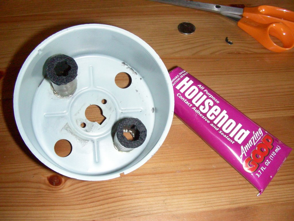 If you look inside the case at the holes the tubes mount to, you'll see that they each have four little locating tabs. The tubes mount around these tabs. We used some good 'ol Goop to cement the tubes to the case; a hour later they were solid as as rock and goin' nowhere. We slid the mechanism back into the case and reinstalled the two case screws; the fit was perfect. Shining my Mini-Maglite into the holes confirmed that everything was sealed up tight.
In cars of this vintage, instrument needles were usually painted orange. Usually, this is faded to nothing by now, and the indicator on our speedo sure was. I've found the best way to re-do these is with a Testors paint marker that you can find at any hobby shop. A couple of quick strokes and you're done.
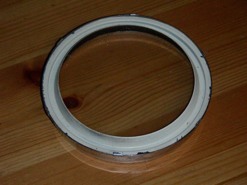 We're almost done, but the bezel needs some attention. On Studes of this vintage, it's actually a three-piece assembly: the chromed outer band, the glass, and a reflector ring. The ring is painted flat black on one side and white on the other, to reflect the light from the instrument lamps back onto the gauge face. We cleaned ours, used some Turtle Wax chrome polish on the bezel, and put the sandwich back together. If your reflector ring has flaking paint (usually it's the flat black side), you'll need to remove the loose paint and give it a quick shot from the rattle-can before reassembling.
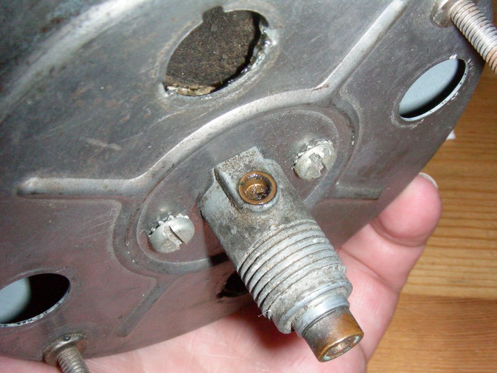 I asked the forum members about lubricating the speedo works, and was told that there's only one place that needs oiling: a little oil port on the input shaft that's visible from outside the case when it's all assembled. You can see it in the photo: a little cup with a felt insert at the bottom. It doesn't need too much oil; I filled it with about three drops of Marvel Mystery Oil (did you know they make an all-purpose lube in a squeeze bottle?) and spun the shaft by hand to work it in.
Final step of the reassembly is to mate the bezel with the case and carefully bend the locking tabs back into place. Remember, go slow or they'll break right off and then you'll be cussin' up a storm.
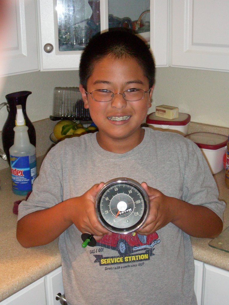
Here it is, ready to go back in the dash... after I replace the wiring harness. (More on that later.)
I promise, all my posts won't be a long as this one. If you made it this far, congratulations! Have a beer on me to celebrate :)
posted by Clark at
8:15 PM
![]()
![]()

0 Comments:
Post a Comment
<< Home